Download
1 / 24
240 likes | 404 Vues
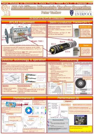
P. Morettini - ATLAS Collaboration. ATLAS Silicon Tracker commissioning. The ATLAS Detector. Liquid Argon calorimeter. Muon Detector. Tile Calorimeter. Muon spectrometer m tracking MDT (Monitored drift tubes) CSC (Cathode Strip Chambers) RPC (Resistive Plate Chamber) Trigger

E N D
P. Morettini - ATLAS Collaboration ATLAS Silicon Tracker commissioning Paolo Morettini - VCI 2010
The ATLAS Detector Liquid Argon calorimeter Muon Detector Tile Calorimeter • Muon spectrometer • m tracking • MDT (Monitored drift tubes) • CSC (Cathode Strip Chambers) • RPC (Resistive Plate Chamber) Trigger • TGC (Thin Gas Chamber) Trigger • 4T Toroid Magnet • 3 Level Trigger system • L1 – hardware – 100 kHz 2.5 ms latency • L2 – software – 3-4 kHz 10 ms latency • EF – software – 100 Hz 1-2 s latency • Inner Detector (ID) • Tracking • Silicon Pixels 50 x 400 mm2 • Silicon Strips (SCT) 80 mm stereo • Transition Radiation Tracker (TRT) up to 36 points/track • 2T Solenoid Magnet • Calorimeter system • EM and Hadronic energy • Liquid Ar (LAr) EM barrel and end-cap • LArHadronic end-cap • Tile calorimeter (Fe – scintillator) hadronic barrel Toroid Magnet Solenoid Magnet SCT Pixel Detector TRT Paolo Morettini - VCI 2010
The ATLAS Inner Detector • Designed to precisely reconstruct charged particles • 7-points silicon (pixels + strips) tracker (|h|<2.5) plus straw tube quasi-continuous tracker with electron identification capability (TRT) (|h|<2). • 2 T solenoidal magnetic field • Momentum resolution: • IP resolution: Paolo Morettini - VCI 2010
The Semiconductor Tracker The SemiConductor Tracker (SCT) is a silicon strip detector. It’s organized in 4 layers barrel, built with 2112 modules and two 9 disks end-caps, made of 1976 modules. The total number of strips is 6.3 106. The end-caps are built with three different modules: • Pitch 57-95 mm • Strip length 55-120 mm • The barrel module consists of four single sided p-on-n strip detectors: • Pitch 80 mm • Strip length 120 mm • Stereo angle 40 mrad Paolo Morettini - VCI 2010
The Pixel Detector • The Pixel Detector is made of 1744 modules (~80 106 channels). • A module is a 6x2 cm2 detector with 46080 read-out channels; the pixel size is 50x400 mm2, but larger pixels are used to cover the space between the FE chips. • It’s connected to the external world via a single (low mass) cable providing all the required services: • Bias voltage • Analog and digital LV • Clock • Serial command line • Serial data outputs • Temperature measurements • The same module is used in the barrel and in the disks: • staves (13 modules along the beam axis) for the barrel. • sectors (6 modules on a two-sided octant) for the disks. Paolo Morettini - VCI 2010
Bump bonds Pixel Detector Module Breakdown PP0 connection Flex Hybrid Sensor tile 16 FE chips Wire bonds Paolo Morettini - VCI 2010
ID Commissioning SCT barrel installation, June 06 The installation in the ATLAS cavern was completed by July 07, but operation with the full detector cooled down was possible only starting from April 08. The preparation for the LHC collision era consisted of three main activities: • Commissioning of the services; in particular the C3F8 evaporative cooling plant, damaged in an accident in May 08, required significant upgrades. Now the cooling system operates in a very stable way (-2o to 4.50C for the SCT, -20oC for the Pixel Detector). • Detector calibration using the internal charge injection mechanism. • Data taking with cosmics. Pixel installation, July 07 Paolo Morettini - VCI 2010
Calibration procedures Pixel Detector opto-link tuning Given the enormous amount of channels and of free parameters to tune, the read-out electronics and the DAQ software were designed with particular attention to the calibration procedures. Just using the internal front-end electronics self-test and charge injection capabilities it’s possible to: • Tune the custom rad-hard opto-link parameters to guarantee error free data transmission. • Adjust the discriminator threshold of each channel to minimize threshold dispersion. • Measure the noise of each channel. • Tune the time-over-threshold (Pixel Detector). Paolo Morettini - VCI 2010
Structure of the pixel read-out cell • The Pixel Detector FE cell contains: • a constant (adjustable) feedback current pre-amp • a discriminator • a 5 bit DAC to adjust threshold • a circuitry to measure time over threshold (ToT) • an analog and a digital injection point Paolo Morettini - VCI 2010
Threshold uniformity Pixel Detector Measuring the discriminator activation curve as a function of the injected charge it’s possible to determine threshold and noise. • The PixelDetector is operated at 3000-4000 e threshold, and the typical noise of regular size pixels is below 200 e. • This large S/N ratio ensures excellent system stability, despite the huge number of channels and the high density. • Similar considerations hold for the SCT; the noise is obviously larger, of the order of 1500 e, but well below the typical threshold set at 1 fC. Pixel Detector Pixel Detector Paolo Morettini - VCI 2010
Noise occupancy • The occupancy due to noise can be calculated from the noise measured with the charge injection, or derived directly with a random trigger. • The agreement between the two methods is good. • The very low noise gives very low occupancies. • SCT occupancy: ~10-5 • Pixel Detector occupancy: ~10-10masking less then 0.02% of the pixels. Pixel Detector 10 -10 Paolo Morettini - VCI 2010
Pixel Detector ToT Calibration The pixel read-out cell can measure (in 25 ns units) the time the discriminator input remains over threshold. This is correlated with the deposited charge. The pixel cell pre-amp feedback current can be adjusted to equalize the ToT response. Pixel Detector Pixel Detector Paolo Morettini - VCI 2010
Data taking with cosmics Cosmics have been taken in two long, dedicated periods; the first in 2008 (in preparation for the first LHC startup, and after September 19 accident) and the second in 2009. In total, several millions of cosmic muons have been detected, about 700k crossing the Pixel Detector. Even if not replacing collisions, cosmic muons were useful to: • align the Inner Detector • test the tracking algorithms and compute hit efficiency • adjust detector timing • test the trigger and data acquisition system 2008 2009 Paolo Morettini - VCI 2010
Alignment The alignment of the ID is performed in subsequent steps, varying the number of degrees of freedom. The first level only compensates for sub-detector global misalignments. The second is used to align sub-detector components and the third aligns the individual mechanical units. Using the cosmics, it was possible to complete the second alignment step and part of the third one in the barrel region. Practically, this level is already close to the ideal alignment, as demonstrated by the comparison of the residuals determined with cosmics events and with a perfectly aligned MC (24 vs 16 mm for the Pixel Detector Barrel, 30 vs 16 mm for the SCT Barrel). Paolo Morettini - VCI 2010
Hit efficiency The hit efficiency of each silicon layer can be measured performing a track fit without that layer and looking for hits aligned with the resultant tracks. Typical hit inefficiencies are of the order of 0.2%. Pixel Detector Barrel Paolo Morettini - VCI 2010
Lorentz angle measurement The Lorentz angle can be calculated as the track incidence angle corresponding to the minimum of the average cluster size. The minimum is at normal incidence when the solenoidal field is off. With field on, the measured values are: SCT:qL = 68.6 ± 0.5 ± 1.6 mrad Pixel Detector:qL = 213.9 ± 0.5 mrad Pixel Detector Paolo Morettini - VCI 2010
Detector timing Both SCT and Pixel Detector have multi-bunch crossing read-out capability (3 consecutive BC for the SCT, from 1 to 16 for the Pixel Detector). This capability increases detector efficiency in the initial phase, when the inter-module timing is not perfectly adjusted, and can be a useful tool to check the relative timing of different trigger components. The goal is to align the modules to 1 ns, as soon as the necessary track statistics will be available. Pixel Detector SCT Paolo Morettini - VCI 2010
First collisions (at last…) After very quick injection and RF capturing commissioning, LHC started to produce pp collisions at 900 GeV on November 23 (!!!!!). In the following days, ATLAS collected 917 k collision candidates at 900 GeV and 34 k at 2.36 GeV (new world record). Thanks to the intense commissioning program, the silicon trackers arrived well prepared to this rendez-vous: 99.3% of strips active for the SCT, 97.9% of pixels active). However, for obvious security concerns, the two detectors were fully on only when stable beams condition was declared (538 k events). Paolo Morettini - VCI 2010
Few events… Paolo Morettini - VCI 2010
Improvements to the alignment One immediate benefit of the first LHC collisions was to bring the alignment of the detector parts less illuminated by the cosmics to the same level of the rest of the detector: SCT Barrel: 43 mm (MC 36 mm) PIX Barrel: 34 mm (MC 22 mm) SCT EC A: 87 mm (MC 46 mm) SCT EC C: 86 mm (MC 46 mm) PIX EC A: 28 mm (MC 24 mm) PIX EC C: 28 mm (MC 25 mm) The impact parameter resolution is consistent with the MC expectations. Paolo Morettini - VCI 2010
Pixel Detector dE/dx measurement The ToT resolution achieved with the internal calibration (15%) is sufficient to distinguish p from K in minimum bias events below 1 GeV/c. p K Paolo Morettini - VCI 2010
Mass peaks with the ID The ID alignment obtained during the commissioning is good enough to identify Ks and L mass peaks in the sample of minimum bias events. The mass values agree with the PDG values, the resolutions with the MC expectations (dominated by multiple scattering). Paolo Morettini - VCI 2010
On-line tracking Another indicator of the decent shape of the silicon tracker comes from the Level 2 trigger algorithms, that are largely based on the silicon components of the ID. These algorithms are simplified compared to the ones used in the off-line, but provide track reconstruction within the 10 ms Level 2 latency. As an example, the center of the beam spot region determined from the d0vsf distribution of the tracks reconstructed on-line is in good agreement with the off-line. results. Paolo Morettini - VCI 2010
More than a conclusion… • After a long and challenging commissioning phase, the ATLAS Silicon Tracker is in very good shape. • 97.9% of the pixels and 99.3% of the SCT strips are operational. • Noise occupancy and hit efficiency exceed the design specifications. • The alignment is already close enough to the ideal one to allow on-line track reconstruction and invariant mass reconstruction. … a new beginning ! • We are ready to start a new, and hopefully successful, LHC run… Paolo Morettini - VCI 2010