Download
1 / 12
350 likes | 1.19k Vues
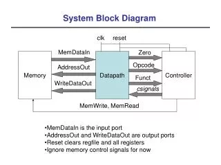
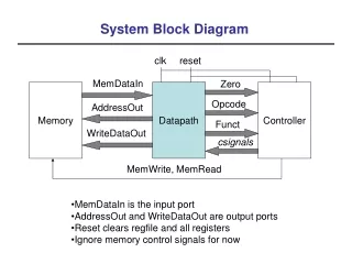
Monochrome Television Block Diagram. Speaker. Picture Tube. Diagram Showing Input and Outputs. Television Receiver. All Section. Power Supply. AC Input. Black and White Television. Sound IF Amplifier. Sound Detector. Audio Amplifier. Speaker. Tuner. Video Amplifiers.

E N D
Speaker Picture Tube Diagram Showing Input and Outputs Television Receiver All Section Power Supply AC Input
Black and White Television Sound IF Amplifier Sound Detector Audio Amplifier Speaker Tuner Video Amplifiers IF Amplifier Video Detector AGC Picture Tube All Stages Vertical Sweep Sync Separator AFC Low Voltage Power Supply High Voltage Power supply Horizontal Oscillator Horizontal Output AC line
Function of each Block Section • Low Voltage Power Supply – this power supply DC voltage in all section of the television. It is also a place used to convert AC voltage to DC voltage. • Sound IF Amp – received and synchronize Sound signal • Sound detector-
Continuation… • Sound detector – filter the signal received from the sound IF amp. • Audio Amplifiers- Amplify signal from the sound detector • Tuner – Select the station or channel that you desire. • Sound IF Amplifiers – received the signal emitted from the sound trap • Video Detector – filter the signal received from the video IF amp • Video Amplifier - Amplify the video received from the video detector section.
Continuation… • AGC • AFC • Sync separator • Vertical Sweep • Horizontal Oscillator • Horizontal Output • High Voltage Power Supply • Picture tube • Deflection Yoke
Color Television Sound Detector Audio Amplifier Sound IF Amplifier Speaker Tuner Video Amplifiers IF Amplifier Video Detector AGC Picture Tube All Stages Vertical Sweep Sync Separator AFC Low Voltage Power Supply High Voltage Power supply Horizontal Oscillator Horizontal Output AC line
Details of Vertical and Horizontal Section High Voltage rectifier Flyback Horizontal Oscillator Horizontal Driver Horizontal Output Filament coil Yoke To Filament Coil 2 Coil 1 Picture Tube Vertical Oscillator All Stages Vertical Output Vertical Driver Low Voltage Power Supply AC line
Horizontal Scanning • Horizontal Scanning - 15.734 Hz • Vertical Scanning – 59 Hz pulse • Interlace scanning – Function of horizontal and vertical • deflection pulls the beam from left to right and the • other force pull from top to bottom. Composed of • 525 lines to complete one picture called frame • 1 lines = 262 lines • 2 lines = 525 equivalent to 1 frame
Composite Video Signal is composed of the following • Video Signal –gives the right image information to the picture tube. ( 30 Hz – 4.2 MHz • Horizontal Blanking pulse – tell the receiver to blank the electron beam • Horizontal synchronizing Pulse • Vertical Blanking Pulse • Vertical synchronizing Pulse • Equalizing pulse