Project X Injector Experiment (PXIE) Overview and Design Adjustments
210 likes | 358 Vues
The Project X Injector Experiment (PXIE) focuses on the development and optimization of a linear accelerator system designed to advance particle physics research. This document outlines reference designs for various energy levels (3 GeV, 8 GeV, 120 GeV) and details modifications in the configuration of the initial 10 MeV acceleration. Key elements include functional requirements for beam currents, extraction sections, and the integration of superconducting radio-frequency technology. Following successful prototype testing, PXIE aims to validate design parameters while collaborating with leading research institutions.

Project X Injector Experiment (PXIE) Overview and Design Adjustments
E N D
Presentation Transcript
Project X Injector Experiment (PXIE) Sergei Nagaitsev Dec 19, 2011
Project X Reference Design 3 MW @ 3 GeV 200 kW @ 8 GeV 2 MW @ 120 GeV 1-GeV extraction section • Reference Design continues as our baseline concept • Modified configuration of initial 10 MeV acceleration (RFQ and HWR) • Functional Requirements Specification (FRS) updated to reflect changes • Project X Document # 658 AEM Dec 19, 2011 - S. Nagaitsev
Reference DesignProvisional Siting CW Linac Pulsed 3-8 GeVLinac based on ILC / XFEL technology Pulsed Linac AEM Dec 19, 2011 - S. Nagaitsev
=0.1 =0.22 =0.4 =0.61 =0.9 =1.0 325 MHz 10-160 MeV 1.3 GHz 3-8 GeV 650 MHz 0.16-3 GeV SRF Linac Technology Map CW Pulsed 162.5MHz2.1-10 MeV AEM Dec 19, 2011 - S. Nagaitsev
Linac beam current:1 mA averaged over ~us Beam to Recycler AEM Dec 19, 2011 - S. Nagaitsev Linac beam current has a periodic time structure (at 10 Hz) with two major components.
Chopping and splitting for 3-GeV experiments 1 msec period at 3 GeV Muon pulses (16e7) 81.25 MHz, 100 nsec at 1 MHz700 kW Kaon pulses (16e7) 20.3 MHz 1540 kW Nuclear pulses (16e7) 10.15 MHz 770 kW Ion source and RFQ operate at 4.2 mA ~75% of bunches are chopped at 2.5 MeV after RFQ Separation scheme Transverse rf splitter AEM Dec 19, 2011 - S. Nagaitsev
Beam after splitter 1 MHz pulses 10 MHz bunches 20 MHz bunches AEM Dec 19, 2011 - S. Nagaitsev
Front-End Test Facility • We are preparing to build a prototype of the first ~30 MeV of Project X. • Validate the concept for the Project X front end, thereby eliminating the primary technical risk element within the Reference Design. • Wideband chopper; low-b acceleration • Operate at full design parameters • Integrated systems test goals: • 1 mA average current with 80% chopping of beam delivered from RFQ • Efficient acceleration with minimal emittance dilution through ~30 MeV • Potential utilization in Project X facility following successful demonstration • Collaboration between Fermilab, ANL, LBNL, SLAC; India & China? • Oct 2016: Beam through b=0.1 , 0.2 CM at ~30 MeV with nearly final parameters (1 mAcw, 5 mA peak, arbitrary bunch chopping) AEM Dec 19, 2011 - S. Nagaitsev
Project X Injector Experiment: PXIE SSR1 HWR MEBT RFQ LEBT LBNL FNAL, SLAC ANLFNAL Dump • CW H- source delivering 5 mA at 30 keV • LEBT with beam pre-chopping • CW RFQ operating at 162.5 MHz and delivering 5 mA at 2.1 MeV • MEBT with integrated wide-band chopper and beam absorbers capable of generating arbitrary bunch patterns at 162.5 MHz, and disposing of 4 mA average beam current • Low beta superconducting cryomodules: 1 mA to 30 MeV • Beam dump capable of accommodating 1.6 mA at 30 MeV(50 kW) for extended periods. • Associated beam diagnostics, utilities and shielding AEM Dec 19, 2011 - S. Nagaitsev
Ion Source • Regardless of the ion source current, the linac beam current is 1 mA • this is achieved by a LEBT and MEBT choppers • The Linac beam starts from an H- ion source operating at a constant current, set for a given timeline: • If MI/Recycler is running, the minimum ion source current is 1.7 mA • If MI/Recycler is NOT running, the minimum ion source current is 1 mA • The nominal ion source beam current used in optics design is 5 mA • The ion source is capable of 15 mA, RFQ and MEBT are designed to 10 mA AEM Dec 19, 2011 - S. Nagaitsev
LEBT • Provides 30-keV beam transport from the Ion Source to the RFQ • chopper • diagnostics AEM Dec 19, 2011 - S. Nagaitsev
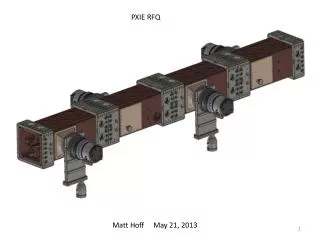
RFQ • Ion type: H- • Beam current: 5 mA (nominal); 1 – 10 mA • Transverse emittance (norm, rms):< 0.25 mm-mrad • Longitudinal emittance (rms):0.8 – 1.0 keV-nsec • Input energy:30 keV • Output energy (kinetic): 2.1 MeV • Duty factor: 100% (CW) • Frequency: 162.5 MHz • Length: ~4.4 m AEM Dec 19, 2011 - S. Nagaitsev
MEBT • Functions of MEBT • Form the bunch structure required for CW Linac • Match optical functions between RFQ and SRF • Include tools to measure the properties of the beam coming out of RFQ and sent to SRF • Protect SRF cavities from accidents AEM Dec 19, 2011 - S. Nagaitsev
MEBT optics RF Kicker RF Kicker Absorber RF Cryomodule AEM Dec 19, 2011 - S. Nagaitsev
PXIE Location PXIE CMTF New Muon Lab AEM Dec 19, 2011 - S. Nagaitsev
PXIE Layout AEM Dec 19, 2011 - S. Nagaitsev
Possible building layout PXIE AEM Dec 19, 2011 - S. Nagaitsev
Goals for FY2012 • CW Linac/PXIE • Conventional facilities • Complete shielded enclosure – ready for equipment installation. • LEBT • Complete design and all parts ordered • Ion source commissioning (at LBNL) • RFQ • Complete design, ready for procurement (LBNL/FNAL) • Specifications complete, ready for procurement: rf& water systems • MEBT • Vacuum prototype chopper kicker tested (bandwidth and average power) • 12 kW prototype beam absorber designed, fabricated and tested (e-beam) • MEBT design 50% complete • HWR, SSR1 Cryomodules(ANL/FNAL) • Cavity design complete, fabrication started • Cryomodule design complete AEM Dec 19, 2011 - S. Nagaitsev
Goals for FY2012 • Pulsed Linac • Complete lattice design • Specifications for alignment and RF tolerances • Failure analysis • Design of the transport lines to/from pulsed linac • Conceptual design of the HLRF system • Systems specifications • Survey of alternatives (klystron, IOT, magnetron) • LLRF performance study for long pulse operation. • Complete conceptual and EM design of splittable SC (focusing) magnet • Conceptual design of the cryogenic systems and specifications • Specifications for beam diagnostics in Linac and transport lines AEM Dec 19, 2011 - S. Nagaitsev
Goals for FY2012 • Experimental Facilities • Prepare for DOE workshop • Preliminary concepts for experimental facilities • Conventional Facilities • Master planning as related to PX siting and utility needs • Consolidation of new project (LBNE, MU2E, PX, g-2) infrastructure • Preliminary design of critical infrastructure needs: • Electrical single lines and load tables • Cooling schematics with input from pond studies; cost analysis of various cooling options (cooling towers, new pond(s), ICW, etc.) • Update siting scenarios against latest wetland studies, • Discipline reviews of CD-0 cost estimate Review and revise RLS to support a CD-0 review • General support of alternate configurations, value engineering and phasing options AEM Dec 19, 2011 - S. Nagaitsev
Summary • Project X R&D program underway with very significant investment in srftechnology • PXIE has been identified as a centerpiece of the program – planning underway • Will address main technical uncertainties with (1) chopper kicker, (2) chopper driver and (3) beam absorber • Integration test of RFQ, MEBT, HWR, SSR1 • Plan to demonstrate by Oct 2016: Beam ~30 MeV with nearly final parameters (1 mAcw, 5 mA peak, arbitrary bunch chopping) AEM Dec 19, 2011 - S. Nagaitsev