Download

1 / 28
290 likes | 563 Vues
Project X Injector Experiment (PXIE). Steve Holmes Fermilab Proton Accelerators for Science and Innovation: Second Annual Meeting Rutherford Appleton Laboratory April 3-5, 2013. Reference Design RDR Link. 3 GeV superconducting, CW linac 3-8 GeV superconducting pulsed linac

E N D
Project X Injector Experiment (PXIE) Steve Holmes Fermilab Proton Accelerators for Science and Innovation: Second Annual Meeting Rutherford Appleton Laboratory April 3-5, 2013
Reference DesignRDR Link 3 GeV superconducting, CW linac 3-8 GeV superconducting pulsed linac Modifications to MI and RR Experimental Facilities Staging Strategy 2013 PASI, S. Holmes
Project X R&D program PXIE • Goal of the R&D Program is to mitigate risk: technical/cost/schedule The unique capabilities of Project X depend largely on the front end, in particular the wideband chopper. • Technical Risks • Front End • CW ion source through SSR1 • H- injection system • Booster in Stage 1, 2; Recycler in Stage 3 • High Intensity Recycler/Main Injector operations • High Power targets • Cost Risks • Superconducting rf • Cavities, cryomodules, rf sources – CW to long-pulse • Goal is to be prepared for a construction start in Q1FY18 2013 PASI, S. Holmes
Project X (Stage 1) Bunch pattern created in the MEBT 1 mA f0/2 1 GeV Transverse RF splitter at 1 GeV 0.91 mA 0.09 mA 1 msec RFQ beam current: 3.64 mA Average Linac beam current: 1 mA 2013 PASI, S. Holmes
Project X (Stage 2) 2 mA f0/4 1 GeV 1 mA 1 mA f0/8 3GeV 0.25 mA 0.5 mA 0.25 mA RFQ beam current: 5.0 mA 0.5msec 2013 PASI, S. Holmes
Superconducting RFTechnology Map PXIE RFQ LEBT b=0.11 MEBT b=0.22 b=0.51 b=0.61 b=0.9 b=1.0 Pulsed RT CW 325 MHz 10-177 MeV 1.3 GHz 3-8 GeV 650 MHz 0.18-3 GeV 162.5 MHz 0.03-11 MeV 2013 PASI, S. Holmes
Project X Injector ExperimentPXIE • PXIE is the centerpiece of the PX R&D program • Integrated systems test for Project X front end components • Validate concept for Project X front end, thereby minimizing primary technical risk element within the Reference Design • Operate at full Project X design parameters • Systems test goals • 1 mA average current with 80% chopping of beam delivered from RFQ • Efficient acceleration with minimal emittance dilution through ~30 MeV • PXIE should utilize components constructed to PX specifications wherever possibile • Opportunity to re-utilize selected pieces of PXIE in PX/Stage 1 • Collaboration between Fermilab, ANL, LBNL, SLAC, SNS, India 2013 PASI, S. Holmes
PXIE Scope • CW H- source delivering 5 mA at 30 keV • LEBT with beam pre-chopping • CW RFQ operating at 162.5 MHz and delivering 5 mA at 2.1 MeV • MEBT with integrated wide-band chopper and absorber • Capable of generating arbitrary bunch patterns at 162.5 MHz, and disposing of 4 mA average beam current • Low beta superconducting cryomodules: 1 mA to ~25 MeV • HWR and SSR1 • Beam dump capable of accommodating 2 mA at 25 MeV (50 kW) for extended periods. • Associated beam diagnostics, utilities and shielding • Extinction measurement to 10-9 (goal) 2013 PASI, S. Holmes
Role of PXIE MEBT SSR1 HWR HEBT RFQ LEBT 40 m, ~25 MeV PXIE will address the address/measure the following: • LEBT pre-chopping • Vacuum management in the LEBT/RFQ region • Validation of chopper performance • Bunch extinction • MEBT beam absorber • MEBT vacuum management • Operation of HWR in close proximity to 10 kW absorber • Operation of SSR with beam • Emittance preservation and beam halo formation through the front end 2013 PASI, S. Holmes
PXIE Status • Technical Components • Ion source operational and characterized (LBNL) • LEBT emittance scanner procurement initiated (SNS) • LEBT solenoids ordered (FNAL) • RFQ design complete and procurements initiated (LBNL) • HWR cavity design complete and procurements initiated; CM design in process (ANL) • SSR1 cavity prototypes characterized; CM design in process (FNAL) • Chopper proof-of-principle prototypes and driver development (FNAL, SLAC) • Infrastructure • Siting established at CMTF • Shielded enclosure under construction 2013 PASI, S. Holmes
Major PXIE Features 2013 PASI, S. Holmes • “Adiabatic optics” – small beta-function variation • Mitigation of space charge • LEBT • LEBT chopper • Supports machine tuning in pulsed mode: Dt ~ 0.5 – 10 ms, frep=60 Hz • RFQ • 162.5 MHz RFQ • freq. low enough for bunch-by-bunch chopping, T 6.2 ns, bandwidth of ~ 1 GHz • MEBT • “Two-kickers chopping” makes chopping possible with present technology • 21 kW beam dump for chopped-out beam • Differential pumping to minimize H2 leakage to the SC cryomodules and RFQ
Major PXIE Features (continue) 2013 PASI, S. Holmes • SC cryomodules operating at 2 K • Solenoidal focusing • Warm gap between cryomodules • Fast vacuum valves at both sides of the cryomodules • RF separation at the top energy for beam extinction studies, f=1.5*162.5 MHz • Can help in measurements of bunch length and longitudinal tails • Instrumentation (not a complete list) • Toroids, BPMs, wire scanners, laser wires, scrapers • Spectrometer at the end of the machine • 50 KW beam dump • can support operation up to 2 mA beam current
Ion Source • CW source at 30 KeV • Minimum current: 1 mA • Nominal current: 5 mA • Maximum current: 15 mA 2013 PASI, S. Holmes
LEBT No BEND in PXIE design 2013 PASI, S. Holmes
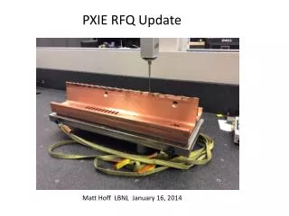
RFQ • Ion type: H- • Beam current: 5 mA (nominal); 1 – 10 mA • Transverse emittance (norm, rms):< 0.25 mm-mrad • Longitudinal emittance (rms):0.8 – 1.0 keV-nsec • Input energy:30 keV • Output energy (kinetic): 2.1 MeV • Duty factor: 100% (CW) • Frequency: 162.5 MHz • Length: ~4.4 m 2013 PASI, S. Holmes
LEBT Beam in LEBT and RFQ Input = Gaussian Beam, Envelopes (3-sigma) RFQ DC beam Neutralized un-neutralized 2013 PASI, S. Holmes
MEBT Beam energy 2.1 MeV Input current 1-10 mA Output current 1 mA Max bunch Frequency 162.5 MHz Bunch-by-bunch selection Chopping system Differential pumping/ scraping Matching from RFQ to MEBT Measure parameters of the beam coming into SRF linac Measure parameters of the beam coming out of RFQ Sections with bunching cavities Specifications and scheme are stable since Jan 2012 2013 PASI, S. Holmes
MEBT #1-Emitttance, laser, Wire scanner, scrapper #0- Scrapper, RF #7-Scrapper, RF, Slow valve, Extinction monitor #8 – Fast valve, DCCT, Toroid, Laser wire, wire scrapper, Scrapper ? Slow valve, Toroid #5-Absorber, OTR #2-Kicker #4-Kicker #6–Diff. pumping, scrapper, wire scanner, #3-Wire scanner, fast Faraday cup, RF Passing beam Chopped beam 2013 PASI, S. Holmes
OpticsRFQ to Beam Dump SC MEBT Diagnostics & Dump HWR SSR1 8 x (S-C) 4 x (C-S-C) Kicker polarity in chopper is set for passing beam 2013 PASI, S. Holmes
HEBT Beam current monitor Emit.diagn. Box: slit, LW/WS 2013 PASI, S. Holmes
PXIE StatusEnclosure 2013 PASI, S. Holmes
PXIE location 2013 PASI, S. Holmes
PXIE time line • Stage 1 complete – early FY17 (~Nov 2016) • Beam delivered to the end of MEBT with nearly final parameters (2.1 MeV, 1 mA CW, 80% arbitrary chopping) • SSR1 tested at full rf power • Stage 2 complete – Aug 2017 • HWR tested at full rf power • Stage 3 complete – Aug 2018 • All elements in place including final kicker and HEBT instrumentation • Beam through HWR and SSR1 2013 PASI, S. Holmes
Summary No change in PXIE design for > 1 year Organization is in place and functioning Developed RLS and adjusted the schedule to align with projected budgets Published the PXIE design handbook 2013 PASI, S. Holmes
Extra Slides 2013 PASI, S. Holmes
PXIE stages • Stage 1: • Ion source, LEBT, prototype chopper • RFQ at full power • Full MEBT with prototype kickers, (possibly) prototype absorber, temp. dump, bunchers, diagnostics • Cryo system • SSR1 CM – cold and rf powered, no beam • Stage 2: • HWR CM – cold and rf powered, no beam • Stage 3: • Full diagnostics line, final MEBT kickers, final 50 kW beam dump, 1-mA CW beam delivered to the dump. 2013 PASI, S. Holmes
PXIE Goals 2013 PASI, S. Holmes • Validate the Project X concept and eliminate technical risks • CW RFQ • Bunch-by-bunch chopper (2 kickers and absorber) • MEBT vacuum level and MEBT/HWR interface • High-current beam acceleration in HWR and SSR1 • Complications can be due to beam loss of RFQ tails in SC linac • Extinction for the removed bunches better than • 10-4 – specified by the PXIE FRS and determined by multi-experiment operation • <10-9 – as desired by m-to-e experiment (no formal specification) • Obtain experience in design and operation of SC proton linac • SSR1 cryomodule will be designed and built by Fermilab
PXIE Summary Schedule 2013 PASI, S. Holmes 28