Download
1 / 24
250 likes | 292 Vues
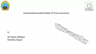
Learn the fundamentals of truss analysis using the Method of Joints and Method of Sections to compute member forces directly from joint equilibrium equations. Discover zero-force members for stability and rigidity improvement.

E N D
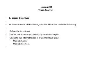
Methods of Analysis Method of Joints Method of Sections The method of section has the basic advantage that the force in almost any desired member may be found directly from an analysis of a section which has cut the member. In choosing a section of the truss, in general, not more than three members whose forces are unknown may be cut, since there are only three available equilibrium equations which are independent. The method of joints utilizes the force equations of equilibrium for each joint. Analysis normally begins at a joint where at least one force is known and not more than two forces are unknown for plane trusses (or not more than three forces are unknown for space trusses)
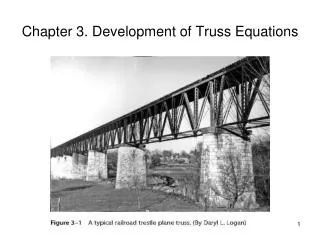
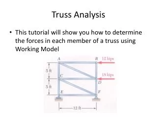
Problem -1 Compute the forces in all the members of the truss, shown here, using the method of joints.
Support Reactions Support Reactions
Calculation of the Member forces Note: For convenience, assume tension in all the members. Remember! A member in compression “pushes” on the joint and a member in tension “pulls” on the joint.
Calculation of the Member forces Member Forces Joint A
Calculation of the Member forces Member Forces Joint B
Calculation of the Member forces Member Forces Joint C
ENGINEERING MECHANICS : STATICS Example 1 (continued): Alternatively, ∑Fx=0 and ∑Fy=0 will give the same results Alternatively, ∑Fx=0 and ∑Fy=0 will give the same results
ENGINEERING MECHANICS : STATICS Example 1 (continued):
Zero Force Members Case 1:If only two non-collinear members form a truss joint and no external load or support reaction is acting at the joint, the members must be zero force members. BC and CD are zero force members. WHY ?????
Zero Force Members (Contd.) Case 2:If there is an external load at the joint, where two members are meeting, and it is acting in the direction of one of the members, another member will be a zero force member. BC is a zero force members. WHY ?????
Zero Force Members (Contd.) Case 3:If three members form a truss joint for which two of the members are collinear, the third member is a zero force member provided no external force or support reaction is acting at the joint. EF is a zero force member. WHY ?????
ENGINEERING MECHANICS : STATICS Zero-Force Members ! Zero-force members are used to increase the stability and rigidity of the truss and to provide support for various loading conditions as well as to support the weight of the truss and to maintain the truss in the desired shape. Although they carry no load, they prevent structural collapse.
Problem-2 Identify zero force members in a truss shown. Answer:BH and DF are zero force members.
Problem-3 60 kN J I H G F • For the truss shown in the Figure, identify all correct zero-force members. 5 m E A C D B 40 kN 5 m 5 m 5 m 5 m
Solution 60 kN J I H G F 5 m E A C D B 40 kN 5 m 5 m 5 m 5 m AB and AJ are zero-force members. JB, JI and IH are also zero-force members. CH is a zero-force member GD is a zero-force member ED is a zero-force member
Example 2: Zero-Force Members For the given loading, determine the zero-force members in the truss shown.
Example 3: Zero-Force Members For the given loading, determine the zero-force members in the truss shown.
Example 4: Zero-Force Members For the given loading, determine the zero-force members in the truss shown.
Example 5: Zero-Force Members For the given loading, determine the zero-force members in the truss shown.