Download
1 / 7
70 likes | 87 Vues
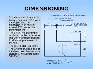
This article discusses problems involving the traces of a line and their projections. It covers the steps to locate trace points on the reference planes, as well as the projections of plane figures. Examples with rectangles and regular pentagons are provided.

E N D
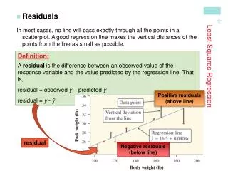
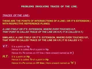
PROBLEMS INVOLVING TRACES OF THE LINE. TRACES OF THE LINE:- THESE ARE THE POINTS OF INTERSECTIONS OF A LINE ( OR IT’S EXTENSION ) WITH RESPECTIVE REFFERENCE PLANES. A LINE ITSELF OR IT’S EXTENSION, WHERE EVER TOUCHES H.P., THAT POINT IS CALLED TRACE OF THE LINE ON H.P.( IT IS CALLED H.T.) SIMILARLY, A LINE ITSELF OR IT’S EXTENSION, WHERE EVER TOUCHES V.P., THAT POINT IS CALLED TRACE OF THE LINE ON V.P.( IT IS CALLED V.T.) V.T.:-It is a point on Vp. Hence it is called Fv of a point in Vp. Hence it’s Tv comes on XY line.( Here onward named as v ) H.T.:- It is a point on Hp. Hence it is called Tv of a point in Hp. Hence it’s Fv comes on XY line.( Here onward named as ’h’ )
b’ FV a’ y x a TV b Observe & note :- 1. Points h’ & v always on x-y line. 2. VT’ & v always on one projector. 3. HT & h’ always on one projector. 4. FV - h’- VT’ always co-linear. 5. TV - v - HT always co-linear. STEPS TO LOCATE HT. (WHEN PROJECTIONS ARE GIVEN.) • Begin with FV. Extend FV up to XY line. • Name this point h’ • ( as it is a Fv of a point in Hp) • 3. Draw one projector from h’. • 4. Now extend Tv to meet this projector. • This point is HT v h’ HT VT’ STEPS TO LOCATE VT. (WHEN PROJECTIONS ARE GIVEN.) • Begin with TV. Extend TV up to XY line. • Name this point v • ( as it is a Tv of a point in Vp) • 3. Draw one projector from v. • 4. Now extend Fv to meet this projector. • This point is VT These points are used to solve next three problems.
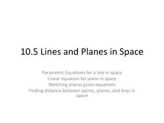
PROJECTIONS OF PLANES In this topic various plane figures are the objects. What is usually asked in the problem? To draw their projections means F.V, T.V. & S.V. What will be given in the problem? • Description of the plane figure. • It’s position with HP and VP. In which manner it’s position with HP & VP will be described? 1.Inclination of it’s SURFACEwith one of the reference planes will be given. 2.Inclination of one of it’sEDGESwithotherreference plane will be given (Hence this will be a case of an object inclined to both reference Planes.)
CASE OF A RECTANGLE – OBSERVE AND NOTE ALL STEPS. For Tv For T.V. For T.V. For Fv For F.V. For F.V. VP VP VP c1’ d1’ d’ a1’ d’ a’ B A C b1’ a’ c’ b’ c’ b’ d1 d1 a1 a d a1 b c b1 b1 c1 c1 HP HP HP ONE SMALL SIDE INCLINED TO VP PICTORIAL PRESENTATION SURFACE INCLINEDTO HP PICTORIAL PRESENTATION SURFACE PARALLELTO HP PICTORIAL PRESENTATION FV-1 FV-2 FV-3 T V-1 T V-2 T V-3 ORTHOGRAPHIC FV- Apparent Shape TV-Previous Shape ORTHOGRAPHIC TV-True Shape FV- Line // to xy ORTHOGRAPHIC FV- Inclined to XY TV- Reduced Shape
A B C Now Complete STEP 2. By making surface inclined to the resp plane & project it’s other view. (Ref. 2nd pair on previous page illustration ) Now Complete STEP 3. By making side inclined to the resp plane & project it’s other view. (Ref. 3nd pair on previous page illustration ) PROCEDURE OF SOLVING THE PROBLEM: IN THREE STEPS EACH PROBLEM CAN BE SOLVED:( As Shown In Previous Illustration ) STEP 1.Assume suitable conditions & draw Fv & Tv of initial position. STEP 2.Now consider surface inclination & draw 2nd Fv & Tv. STEP 3.After this,consider side/edge inclination and draw 3rd ( final) Fv & Tv. ASSUMPTIONS FOR INITIAL POSITION: (Initial Position means assuming surface // to HP or VP) 1.If in problem surface is inclined to HP – assume it // HP Or If surface is inclined to VP – assume it // to VP 2. Now if surface is assumed // to HP- It’s TV will show True Shape. And If surface is assumed // to VP – It’s FV will show True Shape. 3. Hence begin with drawing TV or FV as True Shape. 4. While drawing this True Shape – keep one side/edge ( which is making inclination) perpendicular to xy line ( similar to pair no. on previous page illustration ).
Problem 1: Rectangle 30mm and 50mm sides is resting on HP on one small side which is 450 inclined to HP. Draw it’s projections. Surface // to Hp Surface inclined to Hp d’ c’ c’ d’ a’ b’ b’ a’ 450 X Y a a1 d1 d c b b1 c1
Problem 2: A regular pentagon of 30 mm sides is resting on HP on one of it’s sides with it’s surface 450 inclined to HP. Draw it’s d’ c’e’ b’ a’ c’e’ b’ a’ d’ X Y 450 e1 e e1 a1 a d1 d b b1 c c1