MICE Partial Return Yoke PRY Fabrication
Detailed report on design modifications, cost status, and work progress for the Yoke Pry fabrication project at BNL. Includes procurement updates, structural framework analyses, and assembly procedures.

MICE Partial Return Yoke PRY Fabrication
E N D
Presentation Transcript
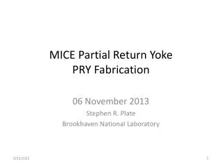
MICE Partial Return YokePRY Fabrication 06 November 2013 Stephen R. Plate Brookhaven National Laboratory
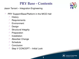
Outline • 6-Section Design Change – update • Cost & Procurement Status • Work to complete
Center sections (independent removal) Lowered Restraint bars (clear mezz, south) Previous design New design Left/right symmetry Add Hall floor (no leg splices, shorter leg) Shorter horizontal reach New leg arrangement
Crossbar positions not final Tie-down bar apertures repositioned Waveguide slots to be angled upward
Bolted leg-channel connections Rail is now intermittent Jacking screw for disassembly (3)
6-Section Design 4° taper L C 1807 kg 3306 kg 1380 kg 3490 kg Lighter color indicates machined areas
Fabrication Cost & Procurement Status • JFE steel order (JFE, Kurashiki, Japan) • 100 mm thick main plates, 50 mm backing plates • Steel of magnetic uniformity • Material total ~$70,000 for 12 plates (8 end, 4 ctr, 8 backing plates) • Delivery: ~16 weeks • Machining • Separate vendor, to be identified • ~$2850, each plate • Framework drawings • Some dwgs. out for quotation • 3 suppliers queried • Awaiting responses
Work to complete • Modifications to shielding plates • Reposition crossbars • Virostek plate extension mounts and flux leakage mitigation parts • Finalize position and size of slots for tracker waveguides (angled, not normal to surface) • Add drilled/tapped holes for bolted connections, hoist rings, crossbar mounts • Assembly and detail drawings for all of the above items • Deflection/Stress Analysis • Recheck new model in ANSYS Workbench • No surprises expected, but need verification • Structural Framework • Assembly and detail drawings for restraints bars & lower support arms
Hoist ring Install Section 1 Clearance to back of channel Machined surfaces on channel mate to pink bar NOTE: Slides 11-14 show old design, but technique remains current Hoist ring spacer provides correct tilt Section 2 is similarly installed
Install Section 3 (and 4) Lower hoist rings removed; guide blocks installed (also shown on isometric, Slide #4) Plate guided into engagement during lowering
Install Restraint Bars All beam-to-channel connections will also be bolted
(Assembly Technique – continued) • … Install Virostek plate extensions • Install spectrometer solenoids and AFC • Build and install shielding on north side, same technique as south side • Install north/south load-sharing cross bars