Download
1 / 14
140 likes | 165 Vues
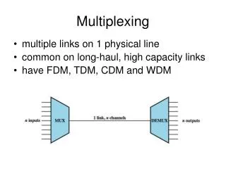
This update provides information on the development of Stavelet, a technology that utilizes chip multiplexing for improved functionality. The Stavelet is being tested with different cooling pipes and various resistance levels. Furthermore, the container for holding the Stavelet along with the flex and quad pixel modules is being built. The multiplexer (mux) used in the Stavelet generates two outputs from four chips and requires a power supply of 2.35-2.6V. However, there are some limitations and complications associated with the current generation flex and mux. Future plans include building more flex hybrids and a demux board for testing connections.

E N D
Four Chip Multiplexing Update Manuel Silva 6 June 2014
Stavelet There are two stavelets that are “fully functional” One uses a titanium cooling pipe the other uses steel The stavelets will be mounted with several quad pixel modules and tested with the cooling pipe at 20°C Trace resistances vary from 0 to 15 Ω
Stavelet Currently building a container to hold the stavelet with the flex and quad pixel modules Stave container for comparison
Mux with four chips Stavelet only has 2 data outputs The mux produces 2 outputs from four chips Aluminum plates under chips and fan used for cooling Muxboard on flex quad module
Multiplexer Channels 1 and 2 output 2.35 V power supply from flex Multiplexer receives 4 signals and outputs 2
Mux four chips Used four functioning chips to test the flux with the multiplexer connected FE-I4B uses 2.0V with maximum value of 2.5V Mux board needs 2.35-2.6V to operate The 2.35V is sufficient to power the flex with the mux but it also generates more heat 2.15A versus 2.00A (shunt mode enabled)
Flex limitations • Current generation flex can only fit two chips on one side • A smaller flex is being developed that can fit all four chips
Stcontrol Change CLK0 in FE Global to “0” (zero) for all demux channels
Stcontrol – analog test Flex with four chips With mux on flex
Complications Stcontrol (trunk) crashes mid scan or post scan for demux settings more often “plot OCCUPANCY” is inconsistent and not entirely reliable Wire bonds are sensitive and chips can only be rebonded about 2-3 times
Future Plans Build more flex hybrids and attach to stavelet Test stavelet with cooling and chips powered Build a demux board to test connections without demux setting on STcontrol