East
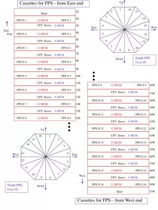
Up. Cassettes for FPS-- from East end. 1. 16. 1E. 2. 15. Spare. 3. 2E. 14. FPS N 1 FPS S 1. 12 MCM. CFT Stereo. 8 MCM. 3E. 4. 13. East. West. East. 4E. East.

East
E N D
Presentation Transcript
Up Cassettes for FPS-- from East end 1 16 1E 2 15 Spare 3 2E 14 FPS N 1 FPS S 1 12 MCM CFT Stereo 8 MCM 3E 4 13 East West East 4E East FPS N 2 FPS S 2 12 MCM 5 12 5E CFT Stereo 8 MCM 6 11 6E 7 FPS N 3 FPS S 3 12 MCM 10 8 9 7E CFT Stereo 8 MCM South FPS (from IP) Down 8E FPS N 4 FPS S 4 12 MCM CFT Stereo 9E 8 MCM FPS N 5 FPS S 5 12 MCM 10E CFT Stereo 8 MCM 11E FPS N 9 FPS S 9 12 MCM 36W FPS N 6 FPS S 6 12 MCM 12E CFT Stereo 8 MCM 37W CFT Stereo 8 MCM 13E FPS N 10 FPS S 10 12 MCM 38W FPS N 7 FPS S 7 12 MCM 14E CFT Stereo 8 MCM 39W CFT Stereo 8 MCM 15E FPS N 11 FPS S 11 12 MCM 40W FPS N 8 FPS S 8 12 MCM 16E CFT Stereo 8 MCM 41W FPS N 12 FPS S 12 12 MCM 42W Up CFT Stereo 8 MCM 43W 16 1 15 2 FPS N 13 FPS S 13 12 MCM 44W 14 3 CFT Stereo 8 MCM 45W 4 13 West East FPS N 14 FPS S 14 12 MCM 46W 12 5 CFT Stereo 8 MCM 47W 11 6 FPS N 15 FPS S 15 12 MCM 48W 7 10 West 9 8 CFT Stereo 8 MCM 49W FPS N 16 FPS S 16 12 MCM 50W North FPS (from IP) Down Spare 51W Cassettes for FPS-- from West end
Proposed Scheme Dec. 16, 1999, (AP) FPS Detector-End Waveguide Routing Scenario(Scanned Image) 16-channel FPS Connector (4x4 Array) Generic FPS Constant -Readout Sector Two 256 (16-channel x 16-channel) bundles radially down the center of a constant -trigger sector (L1, L3) or (L2, L4) [North, South Detector] with each having two eight-connector pigtails routed as shown. Note: a.) From IP: L1(z) > L3(z) and L2(z) > L4(z) where L1, L2=Shower Layers and L3, L4=MIP Layers. b.) In Each Layer (1-4), From IP: v-stereo(z) > u-stereo(z)
(NORTH Front) 128-CHANNELS FPS Clear Waveguide Routing Proposal(FPS Group -- A. Patwa; Created: 12/16/99, Revised: 1/10/00) 64 CHAN 64 CHAN MIP Sector jN L3 North 4-conn 4-conn MIP Sector jN L3 North 1 [3-conn + 1(7-chan) conn] [3-conn + 1(7-chan) conn] (v) (u) 3-conn 3-conn 2 HIGH HIGH L1 and L3 Readout/Trigger Sector (Constant ) North FPS Detector (Symmetric -Sector) 1-conn 1-conn Shower Sector jN L1 North Shower Sector jN L1 North 3 4-conn 4-conn (u) (v) 4 4-conn 4-conn LOW LOW (Sector jN)= (Sector js) (Sector jN)= (Sector js) 4-conn 4-conn Shower Sector jS L1 South 5 Shower Sector jS L1 South (u) (v) 4-conn 4-conn 6 LOW 1-conn 1-conn LOW L1 and L3 Readout/Trigger Sector (Constant ) South FPS Detector (Symmetric -Sector) MIP Sector jS L3 South MIP Sector jS L3 South 7 3-conn 3-conn (u) (v) [3-conn + 1(7-chan) conn] 8 [3-conn + 1(7-chan) conn] 4-conn 4-conn HIGH HIGH LHS RHS VLPC Modules CASSETTE TOP (SOUTH Back) = LOW Gain Cassettes = Partially LOW Gain Cassette Note: 1-conn = 16 FPS channels HIGH Gain Modules: (1,8) (part 2, part 7) LOW Gain Modules: (3,6) (4,5) (part 2, part 7)
1 2 3 4 5 6 7 8 8 MCM Cassette (2 Analog Front End Bd) CFT Left hand bd Right hand bd 64 64 1 8 North (front) 64 64 7 2 64 64 6 3 64 64 4 5 64 64 4 5 South (back) 64 64 6 3 64 64 2 7 Board top Board top 64 64 8 1 Backplane Backplane MCM daughter boards (SIFT+SVX) 64 channels used Warm fiber PORTS 64(E) and 64(W) waveguides /port VLPC chips -- 8 pixels/chip
64 64 64 1 2 3 64 64 64 64 4 5 6 7 8 C1 C2 Cd 12 MCM Cassette (2 AFE Bd) CPS/CFT stereo Left hand bd Right hand bd 64 64 CFT stereo CFT stereo 1 12 North (front) 64 64 CFT stereo CFT stereo 11 2 CPS low 64 CPS low 3 10 4 9 high high CPS low CPS low 5 8 6 7 high high CPS low CPS low 7 6 5 8 South (back) high high CPS low CPS low 9 4 10 3 high high 64 64 CFT stereo CFT stereo 2 11 Board top Board top 64 64 CFT stereo CFT stereo 12 1 Backplane Backplane MCM daughter boards (SIFT+SVX) 64 channels used Warm fiber PORTS 64(E) and 64(W) waveguides /port VLPC
64 64 64 64 C1 C2 Cd FPS from detector to MCM - only shown for 12 MCM AFE right (v) Right hand bd AFE right -- v strips (12 MCM AFE left (u strips) is mirror image, through West ports ) MCMs 55 FPS MIP 55 1E 1 MIP sect j v strips North North (front) 48 48 FPS MIP 2E 2 16 SHWR sect j v strips North 72 FPS Shr low 3 3E 4 high FPS Shr low 72 5 4E 6 high FPS Shr low 72 7 5E SHWR sect j v strips South 8 South (back) high FPS Shr low 72 9 6E 10 high 16 48 FPS MIP 48 7E MIP sect j v strips South 11 55 55 FPS MIP 8E 12 Board top Backplane clear waveguide cables - 16 channels/cable Flex cable Warm fiber connector PORTS 64E (+64W) waveguides /port FPS (v) detector strips VLPC chips 8 pixel/chip
Platform Layout • South & North • BLS • East • L1muon • West • CTT L1 & L2 • cal • Center • BLS • VLPC • SMT • CTT FE center
AFE Crates • Mounted on VLPC Cryostats • Center Row of Platform • LVPS located under cryostats • Each crate has TWO back planes [a&b]
PC03 & PC04 • These two racks are 7” taller • House SMT and CTT sequencer crates • House Mixer and DFE crates for CFT • LVPS located on wall behind racks SS12 SS3 CFT blank CFT Mixer
PC19 & PC20 • House SMT and CTT sequencer crates • House DFE crates for the preshower • LVPS located on wall behind racks FPS SS45
PW03 ,02 & 08 PW02 PW03 • PW08 is to be added outboard of 2 and 3 • PW03 is closest to the center platform • PW03 holds collector boards • PW02 holds the muon trigger crate • Pw08 is reserved for the forward proton
Sequencer Crates • Sequencers & Crates in production • Installation starts soon • CTT installed as part of SMT installation
MCH > M200 - M207 • M200 will hold L2 crates for FPS, CPS & CFT CFT PS
MCH > M209 - M213 • M212 & M213 will look like M210 & M211 • They will hold 4 GS • 3 GS -> CFT & CPS • 1 GS -> FPS GS1 GS3 GS2 GS4
AFE Back Plane • Same BP for 8-MCM and 12-MCM • SQ-5 & 6 not used for 8-MCM • Dual gain channels are on SQ-5 & SQ-6