Download
1 / 3
30 likes | 164 Vues
This guide outlines safety considerations and procedures for sputtering operations, highlighting electrical and mechanical hazards. It emphasizes the importance of grounding all equipment and controlling high voltage via regulated gas pressure. Additionally, it addresses potential pressure explosions from gas cylinders and offers strategies for managing these risks, such as securing bottles and using regulators. Step-by-step procedures for sputtering operations, including system preparation, pressure management, and cleaning techniques, are also included to ensure safe and effective coating processes.

E N D
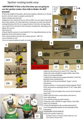
Sputter Stand Safety Specifics • Electrical Hazards • High Voltage : Electrical power is required for the high voltage supply, gauging, system controller and roughing cart. All use 120V@15A. • Mitigate hazard by grounding all equiment including cart / table. Control on/off H.V. via a controller regulating on the gas pressure to ensure optimum range. • Mechanical Hazards • Pressure Explosion: Gas cylinders are used to supply the sputtering gas (Argon, Krypton). • Mitigate hazard by tie up of bottle and using regulators.
Sputtering Operation Procedure • Begin with all electrical equipment unplugged. • Note: All equipment, including the table and chamber or tube, must be grounded at all times • Assemble the necessary vacuum components and Makeup the sealing joints for a complete system. See diagram • Install wire, attached to the H.V. feedthrough and bellows tensioner assembly, through the chamber or tube to be coated. Attach the end of the wire to the end feedthrough flange. • Tension wire by extending bellows then tightening each spring set screw. • Install a new weighted ‘coupon’ thru the window flange. The coupon should lay horizontal, on the bottom of the tube or chamber, parallel to the wire. • Connect the H.V. supply power cord to the controller; also connect the convectron gauge cable. • Connect the H.V. connector cable from the H.V. power supply to the bellows feedthrough. • Plug power cords to electrical outlet with circuit breaker interrupter in line. • Pump down system with roughing cart, Leak check system. • Wrap system for bake out with heat tapes and insulate. • Bake entire system to 250C or as high as possible. Leave system at ~ 150 C so as to sputter at an elevated temperature. • leak check again. No leaks move to next step. • Fill system with sputter gas, pump out and refill to desired pressure for operation. • Turn on discharge in cleaning mode (-H.V). Clean for ~ 30 mins with heating on ~ 150 C. Maintain temperature – the sputtering will heat the system temperature above ~ 100C. ensure it is higher than ~150C.
Sputtering Specifics • POLARITY: • Negative polarity for coating. • Positive polarity for cleaning. • Pressure Range:note- the effective deposition current is dependant on the gas pressure. • Neg Tube: • 2.5KV, 60 mA, 40 – 70 mTorr with Krypton gas. • 2.1 KV, 65mA, 50 – 80 mTorr with Agon gas • Chamber: • 500 -700V, 160mA, 80 - 90 mTorr with Argon gas • Temperature: • 150 – 200 C while coating