Download
1 / 23
230 likes | 255 Vues
R&D for ILD's TPC endplate focusing on material reduction while ensuring precision & stability. ANSYS used for simulations.

E N D
Development of a Low-Material TPC Endplate for ILD Dan Peterson Laboratory for Elementary-Particle Physics, Cornell University 20110319-ALCPG11-Peterson
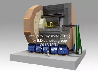
The ILD central tracker is a TPC with outer radius 1808 mm inner radius 329 mm half length 2350 mm Reporting on R&D toward the mechanical endplate of the ILD TPC which, along the way, involves a new endplate for the LCTPC LP and other small prototypes. 20110319-ALCPG11-Peterson
Goals of the ILD TPC endplate Detector module design: consistent with the implementation of Micro Pattern Gas Detector (MPGD) readout modules. Detector elements must provide near-full coverage of the endplate. Detector modules must be replaceable without removing the endplate. Low material - limit is set by ILD endcap calorimetry and PFA: 25% X0 including readout plane, front-end-electronics, gate 5% cooling 2% power cables 10% mechanical structure 8% Rigid - limit is set to facilitate the coupled alignment of magnetic field and module positions. Precision and stability of x,y positions < 50μm ILD will give us 10cm of longitudinal space between the gas volume and the endcap calorimeter. 20110319-ALCPG11-Peterson
In 2008, Cornell constructed two endplates for the LCTPC Large Prototype (LP1). These were shipped August 2008 and February 2010, and are currently in use. Inside the chamber Outside the chamber The endplate construction was developed to provide the precision required for ILD, precision features are accurate to ~30 μm, but not to meet the material limit specified for the ILD TPC; the bare endplate has mass 18.87 kg over an area of 4657 cm2, (mass/area) / (aluminum radiation length (24.0 g/cm2) ) = 0.169 X0. The accuracy was achieved with a 5-step machining process developed at Cornell. 20110319-ALCPG11-Peterson
Where is all that mass? Much material is in the thick un-instrumented areas. This will not exist in ILD; it goes away for free. Much is in an outer stiffening flange; this concentrated material at the barrel/endcap interface is undesirable. Much is in the stiffened mullion structure. There is additional material in the module frames. 20110319-ALCPG11-Peterson
ANSYS calculations have been used to study the effects of lightening various parts of the endplate. The stiffness is characterized by the maximum deflection due to a 100N load (22 lbs) (2.1 millibar overpressure). lighten outer flange max. deflection mass LCTPC LP1 (standard) 33 μm 18.87 kg (1) thin uninstrumented area 51 μm 11.63 kg further simulations, starting with the baseline “(1) thin uninstrumented area” ∆ max. deflection ∆ mass (1)+(2) lighten outer flange +17 μm -2.70 kg (1)+(3) remove outer stiffening ring +15 μm -0.88 kg (1)+(2)+(3) +29 μm -3.11 kg (1)+(4) remove aluminum stiffening (module support) +81 μm -1.58 kg (1)+(2)+(4) +117 μm -4.28 kg remove outer stiffening ring thin uninstrumented area ►“lighten outer flange” has a effect similar to “remove outer stiffening ring” with a greater mass saving . ► “remove aluminum stiffening (module support)” causes a significant change in stiffness. The replacement with some other structure is necessary to maintain the stiffness. remove aluminum stiffening (module support) 20110319-ALCPG11-Peterson
location number 0 -1 1 2 -2 -3 3 “deflection 1” 4 -4 5 -5 6 -6 -7 7 “deflection 2” Stress is <1% yield. In the first validation of the FEA, deflection of the current LP1 endplate was measured and compared to the FEA. The load of 100N (22lbs) was placed “uniformly” in the center module location. Deflection, measured across 2 lines, agrees on average. 20110319-ALCPG11-Peterson
It is possible to reduce the material in the LP1 endplate from 18.85kg to 7.35kg or 16.9% X0 to 6.5 X0, with a deflection increase to from 51 μm to 117 μm. But, when the lightened endplate design (or even the pre-lightened design) is scaled up to the ILD endplate the deflections will be much larger. The basic design must be changed to provide the rigidity for the ILD. In this study, a few designs for the ILD endplate will be considered. Computer-Aided-Design to model these designs and Finite-Element-Analysis to evaluate the designs of the ILD endplate and prototype sections of the ILD (where an LP1 endplate is one such section) . Prototypes of sections (including a new LP1 endplate) will be constructed and compared to the results of the FEA, to validate the FEA of the models, and understand complexities of the designs. Note that I am typically using longitudinal stiffness to characterize the strength, when we are ultimately concerned about lateral stiffness and stability. Longitudinal stiffness is readily measured in the prototypes; for now, it gives an indication of the relative lateral stiffness and stability. Stability will be monitored in longer term studies of a new LP1 endplate. 20110319-ALCPG11-Peterson
An early thought was the aluminum/carbon-fiber hybrid design This design, alone, does not provide enough rigidity when scaled up to the ILD. But, it could supplement the strength of another design. In the hybrid design of the LP1 endplate, 1.58 kg of aluminum is replaced by 1.29 kg of carbon. The stiffening bars for module support (see slide 6) are restored. The aluminum contribution to the material 0.014 X0 is replaced by 0.006 X0. The total is 0.072 X0in the hybrid design ( 6.5% from previous slide + 0.6%) . (Does not include modules and electronics.) The plan is that the endplate will serve as part of the mold. The endplate is channeled, extra molds parts are attached, the mold is filled with cast-in-place carbon fiber, and re-machined. Autoclaving would change the aluminum properties. 20110319-ALCPG11-Peterson
Another design considered is a space-frame. In this particular design, adjustable struts are used to precisely align and flatten the endplate, and there is a simple flat back-plane. A space-frame design can significantly improve strength using the entire available longitudinal length as a moment arm. 20110319-ALCPG11-Peterson
Comparison of candidate models: Al/Carbon-Fiber and Space-Frame mass material deflection stress kg %X0 microns Mpa (yield: 241) LP1 18.87 16.9 33 1.5 Lightened 8.93 8.0 68 3.2 (all aluminum) ( “(1)+(2)” from slide 6 ) Lightened Al 7.35 7.2 (68-168) (3.2-4.8) (Al-C hybrid) C 1.29 Channeled Al 7.35 6.5 168 4.8 (all aluminum) ( “(1)+(2) +(4)” from slide 6 ) Space-Frame 8.38 7.5 23 4.2 Material: space-frame has slightly more material than the Al/C hybrid. Deflection: space frame is more rigid than LP1, ~3x more rigid than the lightened (all Aluminum), and (3 to 7)x more rigid than the Al-C hybrid. 20110319-ALCPG11-Peterson
FEA of the LP1 designs gives predictions of the strength of each design, but there are uncertainties in these predictions: …uncertainty about the effectiveness of the carbon-fiber in the hybrid design, …uncertainty about the ability of the FEA to model the joints in the space-frame design. To address these questions, small test sections were designed , constructed, measured, and compared to the FEA. (1) LP1 (2) Al-carbon-fiber hybrid discussed earlier (3) “strut” space-frame as discussed (4) “equivalent-plate” space-frame (described on the next slide) Each is 750 mm long ( LP1 diameter is 770mm ) and represents a section of the LP1 endplate. 20110319-ALCPG11-Peterson
The “equivalent-plate” space-frame was designed as an alternative simple model the “strut” space-frame. The “strut” space-frame model of the full ILD endplate is to big to measure in the FEA. Detailed features are too small compared to the overall dimensions. The plates are adjusted to provide equivalent strength in both the small test section (previous slide) and in the LP1 model. 20110319-ALCPG11-Peterson
Each solid model that was used for the FEA was converted to a an assembly mode for construction. 100 mm The “equivalent plate” spaceframe was constructed in carbon-fiber. 20110319-ALCPG11-Peterson 14
Comparison of deflection for small test beams: FEA vs. measured 20100408 20101105 20101111 20101104 20110202 20110316 uniform load center load center load center load center load mass FEA FEA MEASURED MEASURED MEASURED kg mm/100N mm/100N mm/100N mm/100N mm/100N LP1 0.63 0.48 0.755 0.88 0.75 0.78 Al-C hybrid ( 1.0 part fiber : 1 epoxy ) 1.71 Al-C hybrid ( 0.25 part fiber : 1 epoxy ) 2.12 LP1 (channeled) 0.37 1.33 2.224 2.40 (channeled for the hybrid, but without adding carbon) space-frame (“strut”) 0.76 0.09 0.111 0.11 0.12 space-frame (“equivalent-plate”) 0.111 0.14 The standard LP1 beam agrees with the FEA, except for some problems in the first measurement, probably sloppy centering the load. The “strut” space-frame agrees with the FEA. The model accurately predicts the strength at the joints and the design is useful for ILD. The “equivalent-plate” space-frame was made with commercial carbon-fiber plates that were claimed to have the modulus of aluminum; the modulus is ~20% low. The cast-in-place carbon-fiber does not come close to having the modulus of aluminum. The aluminum/carbon-fiber design will not be considered further. 20110319-ALCPG11-Peterson
Deflection of the “strut” space-frame agrees with the FEA in detail. 20110319-ALCPG11-Peterson
The next phase of prototyping in the ILD endplate study will be construction of a fully functional LP1 endplate in a space-frame design. This will probably be a “strut” space-frame, but “equivalent plate” is still in consideration. (The plate thickness can be increased to compensate for the lower modulus.) The solid model has been converted to an assembly model. 20110319-ALCPG11-Peterson
Other close-up views of the new LP1 endplate, with field-cage-termination and module back-frames. There are also plans to build a limited number of significantly reduced-material module back-frames. Back-frames contribute about 4% X0. 20110319-ALCPG11-Peterson
construction schedule Model work requires about 2 weeks, mostly fillets and fine tuning. Drawing is nearly complete. Vendor has been contacted to discuss some of the details. Expect completion of parts (main-plate, back-plate, struts) July 2011 Assembly will require ~2 months Measurements ~ 2 months Then it will be ready for implementation in LP1. An “equivalent plate” endplate also will be produced if funds permit. 20110319-ALCPG11-Peterson
(inside view) The ILD endplate has been modeled in the “equivalent-plate” space-frame design. It could be modeled with the “strut” design, but even a partially populated model in the “strut” design can not be successfully analyzed in the FEA. The “equivalent-plate” is expected to provide equivalent results. (Discrepancy seen in the small test beams is attributed to the modulus of the carbon fiber.) This model has a full thickness of 100mm, radius 1.8m, and a mass of 136kg. the thickness is then 1.34g/cm2, 6%X0. 20110319-ALCPG11-Peterson
FEA calculations of deflection and stress (stress is not shown) Endplate Support: outer and inner field cages deflection=0.00991 mm/100N (area of ILD)/(area of LP1) =21.9 deflection for 2.1 millibar over the ILD TPC endplate (2200N) = 0.22 mm Without the spaceframe, the simple endplate deflects by 50mm. strength vs thickness It was expected that the strength could be improved by asking ILD for more longitudinal space. However, the rate of improvement decreases above 100mm thickness, Note small buckling in inner layer. Strength is improved with modest increase in the back-plate thickness. 20110319-ALCPG11-Peterson
Summary: the design of the ILD endplate utilizes prototypes at different scale (ILD, LP1, small beams) and different levels of development (modeling and construction, as well as FEA). Each provides a piece of the information for the design. levels of development simplified models Construction detailed models FEA Simple beam prototypes scale Calibrate the model to reality Calibrate simplified model LP1 endplate July 2011 Use the LP1 experience to understand complexity, stability. ILD endplate 20110319-ALCPG11-Peterson
Summary There has been modeling and FEA at several scales of ILD development: small beams, LP1, ILD. The space-frame design is expected to provide the required strength and is a viable construction. A “strut” space-frame version of the LP1 endplate will be constructed this summer for further study of this possible ILD design. lateral strength and stability: much more work is required The new space-frame version of the LP1 endplate will be used in this study. The preliminary ILD spaceframe design can provide 0.22 mm deflection (2.1 millibar overpressure) with a contribution of 6% X0 material (bare endplate) and 2% X0 from the module back-frames. 20110319-ALCPG11-Peterson