Assembling a Functional Multi-Wire Proportional Counter - Page 1
50 likes | 257 Vues
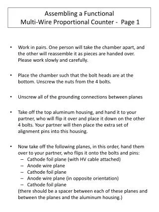
Assembling a Functional Multi-Wire Proportional Counter - Page 1. Work in pairs. One person will take the chamber apart, and the other will reassemble it as pieces are handed over. Please work slowly and carefully.

Assembling a Functional Multi-Wire Proportional Counter - Page 1
E N D
Presentation Transcript
Assembling a Functional Multi-Wire Proportional Counter - Page 1 • Work in pairs. One person will take the chamber apart, and the other will reassemble it as pieces are handed over. Please work slowly and carefully. • Place the chamber such that the bolt heads are at the bottom. Unscrew the nuts from the 4 bolts. • Unscrew all of the grounding connections between planes • Take off the top aluminum housing, and hand it to your partner, who will flip it over and place it down on the other 4 bolts. Your partner will then place the extra set of alignment pins into this housing. • Now take off the following planes, in this order, hand them over to your partner, who flips it onto the bolts and pins: • Cathode foil plane (with HV cable attached) • Anode wire plane • Cathode foil plane • Anode wire plane (in opposite orientation) • Cathode foil plane (there should be a spacer between each of these planes and between the planes and the aluminum housing.)
Assembling a Functional Multi-Wire Proportional Counter - Page 2 • As you handle the anode wire planes, be sure and carefully look at how thin they are and how they are glued into place. Do not attempt to touch the wires because this will destroy them! • After the final aluminum housing is put into place, then put on the nut and tighten the layers together. Reattach the grounding wires. • Prepare the gas line: • Unscrew the gas cylinder cap • Carefully screw in the regulator. Tighten it with a wrench about ¼ turn. • Put the brass compression fitting on the end of the black flexible hose, with the inner collar and the screw threads facing out. • Move them to the end of the hose and hand tighten them onto a compression barrel piece. • Use two wrenches to tighten the hose onto the barrel in the chamber by at least a ¼ turn.
Assembling a Functional Multi-Wire Proportional Counter - Page 3 • Turn on gas supply knob so that the high pressure side of the regulator reads 1000 psi or more. • Adjust the low pressure side of the regulator so that it reads about 5-10 psi • Attach the HV lines from each of the three cathode planes to the chamber distribution box. Attach the HV line from the NIM HV supply (‘A’ on the back) to the distribution box. • Turn the knob on the NIM power supply ‘A’ all the way to the left. Set the full scale current setting to 10 microAmps. Turn on supply ‘A’. • Read the setting by measuring the voltage output at the front panel (1 V read back = 1 kV actual). • Slowly turn on the supply. If the needle on the current gauge begins a runaway increase, back down on the voltage. • Over a period of a few minutes, bring up to 2.7 kV. ( The current should be less than 100 nAmps.
Assembling a Functional Multi-Wire Proportional Counter - Page 4 • Bring radioactive beta source (either Sr-90 or Ru-106) close to the chamber. Can you see the current needle move on its most sensitive setting (100 nA)? • Plug in Nanometrics amplifier/discriminator card to any desired connector, with LV connection away from the chamber. Turn on +/-5V supply. • Take 16 channel ribbon cable from Nanometrics output to the ECL/NIM converter in the NIM crate. • Read each channel’s rate by connecting output to scaler. • Bring source over wires and see if rate increases.