I on source RF system
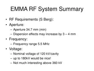
I on source RF system. Andy Butterworth BE/RF Mauro Paoluzzi BE/RF. System description. Wideband solid-state drivers 2 MHz ±200 kHz, 100 kW final stage 2 ms burst at 2 Hz or 50 Hz 50Hz requires power supply upgrade Wideband 1÷1 isolation transformer Capacitive matching network

I on source RF system
E N D
Presentation Transcript
Ion source RF system Andy Butterworth BE/RF Mauro Paoluzzi BE/RF Linac4 ion source review
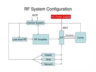
System description • Wideband solid-state drivers • 2 MHz ±200 kHz, 100 kW final stage • 2 ms burst at 2 Hz or 50 Hz • 50Hz requires power supply upgrade • Wideband 1÷1 isolation transformer • Capacitive matching network • PLC control and interlock system • Forward power controlled by AVC servo system • Frequency agile operation compensates plasma detuning effects • High directivity (30dB) directional coupler for plasma electrical characteristics on line measurement Linac4 ion source review
Present status • Two RF systems installed: • Production source in operation in Linac4 • Development source in operation in the 3MeV test stand. • Spares of all critical items are available (custom built or long lead time) • screen pulsers, HV capacitors etc. • Integrated in the control system • interlock, ON/OFF controls, etc. • Integrated in Beam Interlock System • veto from BIS can cut source RF • New low-level control system: • RF reference signal generation • function generation for forward power programming • Remote data acquisition and treatment in control system: • acquisition of RF forward, reflected and plasma light signals • amplitude and phase detection • on-line signal processing and calculation of plasma electrical characteristics (RPlasmaLPlasma and PPlasma) Linac4 ion source review
RF low-level control • A system for RF signal generation and acquisition has been implemented • Uses standard CERN VME controls hardware: • 2-channel arbitrary waveform generator for RF frequency reference and amplitude control function • high speed digitizer for signal acquisition at 50 Msample/s • timing receiver for synchronization with the control system • CPU board running Linux • custom FESA software for signal generation and processing Linac4 ion source review
RF signal generation • Freely programmable frequency and amplitude functions edited using control system (InCA) • Fine-tuning of frequency and amplitude along the pulse allows compensation of plasma detuning effects • Settings management (history etc.) via control system • Waveforms calculated in the front-end computer FESA software • Programmed into 100 Msample/s arbitrary waveform generator Frequency reference signal Frequency AVC reference function (logarithmic) Amplitude Linac4 ion source review
Signal acquisition and processing • Direct sampling of signals at 50 Msamples/s (pulse by pulse): • directional coupler forward • directional coupler reflected • plasma light signal • Forward & reflected signals are demodulated in software into I (in-phase) and Q (quadrature): Coupler fwd Samples Mixer Coupler signal Notch filter fwd I Baseband I signal s Local oscillator (generated RF signal) 90 deg phase shift fwd Q Coupler signal Notch filter Baseband Q signal s Linac4 ion source review
Signal acquisition and processing • From I and Q signals of coupler forward/reflected, derive: • forward/reflected power • phase difference forward/reflected • Using equivalent circuit model (M. Paoluzzi) estimate: • plasma impedance • plasma power • power loss • … W Pfwd Pref Pplasma fwd/ref deg s s Linac4 ion source review
Remaining work for low level RF controls • Make selected signal acquisitions available in standard CERN framework (OASIS) – few days, in progress • Validate online calculation of plasma parameters and calibrate – few days, in progress • Clean up some control system details (function timebase units, device names etc.) – at suitable opportunity • Provide comprehensive user documentation – in progress Linac4 ion source review
Resources needed for source operation • Operation of the two sources for: • Stable production for the Linac4 • Components development for the 3MeV test stand. • Each component is to be validated in the development source before installation in the production one. This requires a number of iterations for matching network design, construction and overall characterization. • Parts installed in Linac4 have limited lifetime and spares must be prepared. They probably also include dedicated matching network parts fitting the specific antenna coil. • For each iteration two days from RF engineer/technician are required. Linac4 ion source review
Summary • High level RF system: • development is complete • installed in Linac4 as well as in 3MeV test stand • spares of all critical items available • resources still needed to support the ongoing development of the source • “Final” Linac 4 RF generation and measurement system has been implemented • uses standard BE/CO hardware components and software framework • flexible control of RF frequency and amplitude • remote RF signal measurements and parameter calculation • small amount of additional functionality still being implemented • All RF equipment integrated into the control and Beam Interlock systems Linac4 ion source review