WAVE OPTICS - I
230 likes | 436 Vues
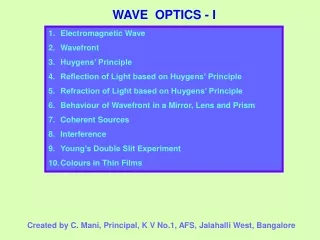
WAVE OPTICS - I. Electromagnetic Wave Wavefront Huygens’ Principle Reflection of Light based on Huygens’ Principle Refraction of Light based on Huygens’ Principle Behaviour of Wavefront in a Mirror, Lens and Prism Coherent Sources Interference Young’s Double Slit Experiment

WAVE OPTICS - I
E N D
Presentation Transcript
WAVE OPTICS - I • Electromagnetic Wave • Wavefront • Huygens’ Principle • Reflection of Light based on Huygens’ Principle • Refraction of Light based on Huygens’ Principle • Behaviour of Wavefront in a Mirror, Lens and Prism • Coherent Sources • Interference • Young’s Double Slit Experiment • Colours in Thin Films Created by C. Mani, Principal, K V No.1, AFS, Jalahalli West, Bangalore
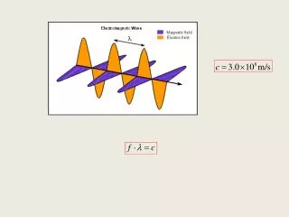
0 Electromagnetic Wave: Y E0 X B0 Z • Variations in both electric and magnetic fields occur simultaneously. Therefore, they attain their maxima and minima at the same place and at the same time. • The direction of electric and magnetic fields are mutually perpendicular to each other and as well as to the direction of propagation of wave. • The speed of electromagnetic wave depends entirely on the electric and magnetic properties of the medium, in which the wave travels and not on the amplitudes of their variations. Wave is propagating along X – axis with speedc = 1 / √μ0ε0 For discussion of optical property of EM wave, more significance is given to Electric Field, E. Therefore, Electric Field is called ‘light vector’.
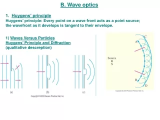
Wavefront: A wavelet is the point of disturbance due to propagation of light. A wavefront is the locus of points (wavelets) having the same phase of oscillations. A line perpendicular to a wavefrontis called a ‘ray’. Cylindrical Wavefront from a linear source Spherical Wavefront from a point source • Plane Wavefront Pink Dots – Wavelets Blue Envelope– Wavefront Red Line – Ray
. . . . . . . . . Huygens’ Construction or Huygens’ Principle of Secondary Wavelets: . . . . • S . . New Wave-front (Plane) New Wavefront (Spherical) . . (Wavelets - Red dots on the wavefront) • Each point on a wavefront acts as a fresh source of disturbance of light. • The new wavefront at any time later is obtained by taking the forward envelope of all the secondary wavelets at that time. Note:Backward wavefront is rejected. Why? Amplitude of secondary wavelet is proportional to ½ (1+cosθ). Obviously, for the backward wavelet θ = 180° and (1+cosθ) is 0.
EF FG t = + c c FC sin r AF sin i + t = c c AC sin r + AF (sin i – sin r) t = c Laws of Reflection at a Plane Surface (On Huygens’ Principle): If c be the speed of light, t be the time taken by light to go from B to C or A to D or E to G through F, then N N D B E G r i i r X Y A C F AB – Incident wavefront CD – Reflected wavefront XY – Reflecting surface For rays of light from different parts on the incident wavefront, the values of AF are different.But light from different points of the incident wavefront should take the same time to reach the corresponding points on the reflected wavefront. So, t should not depend upon AF. This is possible only if sin i – sin r = 0. i.e.sin i = sin ror i = r
EF FG t = + c v FC sin r AF sin i + t = c v sin i sin r AC sin r ) + AF ( - t = v c v sin i sin i sin r sin r = - = 0 c c v v sin i c = = μ v sin r Laws of Refraction at a Plane Surface (On Huygens’ Principle): If c be the speed of light, t be the time taken by light to go from B to C or A to D or E to G through F, then N N B Rarer E c, μ1 i i C F X Y r A Denser v, μ2 G r D AB – Incident wavefront CD – Refracted wavefront XY – Refracting surface For rays of light from different parts on the incident wavefront, the values of AF are different.But light from different points of the incident wavefront should take the same time to reach the corresponding points on the refracted wavefront. So, t should not depend upon AF. This is possible only if or or
Behaviour of a Plane Wavefront in a Concave Mirror, Convex Mirror, Convex Lens, Concave Lens and Prism: C A A C D B B D Concave Mirror Convex Mirror C A A C D B B Convex Lens Concave Lens D AB – Incident wavefrontCD – Reflected / Refracted wavefront
A C D B Prism Prism AB – Incident wavefrontCD –Refracted wavefront Coherent Sources: Coherent Sources of light are those sources of light which emit light waves of same wavelength, same frequency and in same phase or having constant phase difference. • Coherent sources can be produced by two methods: • By division of wavefront (Young’s Double Slit Experiment, Fresnel’s Biprism and Lloyd’s Mirror) • By division of amplitude (Partial reflection or refraction)
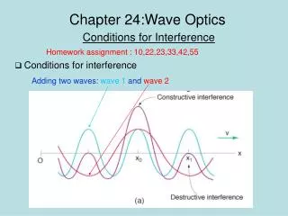
Interference of Waves: Crest Trough Bright Band Dark Band 1st Wave (E1)2nd Wave (E2)Resultant WaveReference Line Bright Band E1 + E2 E1 Dark Band S1 • E2 Bright Band S2 • Dark Band Constructive Interference E= E1+E2 E1 Bright Band E1 - E2 E2 Destructive Interference E = E1-E2 The phenomenon of one wave interfering with another and the resulting redistribution of energy in the space around the two sources of disturbance is calledinterference of waves.
Theory of Interference of Waves: b A θ Φ a b sin Φ tan θ = a + b cos Φ The waves are with same speed, wavelength, frequency, time period, nearly equal amplitudes, travelling in the same direction with constant phase difference of Φ. ω is the angular frequency of the waves, a,b are the amplitudes and E1, E2 are the instantaneous values of Electric displacement. E1 = a sin ωt E2 = b sin (ωt + Φ) Applying superposition principle, the magnitude of the resultant displacement of the waves is E = E1 + E2 E = a sin ωt + b sin (ωt + Φ) E = (a + b cos Φ) sin ωt + b sin Φ cos ωt Puttinga + b cos Φ= A cos θ b sin Φ= A sin θ (where E is the resultant displacement, A is the resultant amplitude and θ is the resultant phase difference) A sin θ b sin Φ We get E = A sin (ωt + θ) A = √ (a2 + b2 + 2ab cos Φ) b cos Φ A cos θ
A = √ (a2 + b2 + 2ab cos Φ) Intensity I is proportional to the square of the amplitude of the wave. So, I α A2 i.e. I α (a2 + b2 + 2ab cos Φ) Condition for Constructive Interference of Waves: For constructive interference, I should be maximum which is possible only if cos Φ = +1. i.e.Φ = 2nπ where n = 0, 1, 2, 3, ……. Corresponding path difference is ∆ = (λ / 2 π) x 2nπ ∆ = n λ Imaxα (a + b)2 Condition for Destructive Interference of Waves: For destructive interference, I should be minimum which is possible only ifcos Φ = - 1. i.e.Φ = (2n + 1)π where n = 0, 1, 2, 3, ……. Corresponding path difference is ∆ = (λ / 2 π) x (2n + 1)π ∆= (2n + 1) λ / 2 Iminα (a - b)2
Imax (a + b)2 (a/b + 1)2 = = (a/b - 1)2 Imin (a - b)2 Imax (r + 1)2 = Imin (r - 1)2 (a1)2 I1 w1 = = I2 (a2)2 w2 Comparison of intensities of maxima and minima: Imaxα (a + b)2 Imin α (a - b)2 where r = a / b (ratio of the amplitudes) Relation between Intensity (I), Amplitude (a) of the wave and Width (w) of the slit: I α a2 a α√w
Young’s Double Slit Experiment: • S • S Single Slit Double Slit P y Screen S1 d/2 d O d/2 S2 D The waves from S1 and S2 reach the point P with some phase difference and hence path difference ∆ = S2P – S1P S2P2 – S1P2 = [D2 + {y + (d/2)}2] - [D2 + {y - (d/2)}2] ∆ (2D) = 2 yd ∆ = yd / D (S2P – S1P) (S2P + S1P) = 2 yd
Positions of Bright Fringes: Positions of Dark Fringes: For a bright fringe at P, ∆ = yd / D = nλ where n = 0, 1, 2, 3, … For a dark fringe at P, ∆ = yd / D = (2n+1)λ/2 where n = 0, 1, 2, 3, … y = (2n+1) D λ / 2d y = n D λ / d For n = 0, y0 = 0 For n = 1, y1 = D λ / d For n = 2, y2 = 2 D λ / d …… For n = n, yn = n D λ / d For n = 0, y0’ = D λ / 2d For n = 1, y1’ = 3D λ / 2d For n = 2, y2’ = 5D λ / 2d ….. For n = n, yn’ = (2n+1)D λ / 2d Expression for Dark Fringe Width: Expression for Bright Fringe Width: βD = yn – yn-1 = n D λ / d – (n – 1) D λ / d = D λ / d βB = yn’ – yn-1’ = (2n+1) D λ / 2d – {2(n-1)+1} D λ / 2d = D λ / d The expressions for fringe width show that the fringes are equally spaced on the screen.
Distribution of Intensity: Suppose the two interfering waves have same amplitude say ‘a’, then Imaxα (a+a)2 i.e. Imaxα 4a2 All the bright fringes have this same intensity. Imin = 0 All the dark fringes have zero intensity. Intensity y y 0 Conditions for sustained interference: • The two sources producing interference must be coherent. • The two interfering wave trains must have the same plane of polarisation. • The two sources must be very close to each other and the pattern must be observed at a larger distance to have sufficient width of the fringe. (D λ / d) • The sources must be monochromatic. Otherwise, the fringes of different colours will overlap. • The two waves must be having same amplitude for better contrast between bright and dark fringes.
Colours in Thin Films: It can be proved that the path difference between the light partially reflected from PQ and that from partially transmitted and then reflected from RS is ∆ = 2μt cos r A C i Q P O B μ t r Since there is a reflection at O, the ray OA suffers an additional phase difference of π and hence the corresponding path difference of λ/2. S R For the rays OA and BC to interfere constructively (Bright fringe), the path difference must be (n + ½) λ So, 2μt cos r = (n + ½) λ For the rays OA and BC tointerfere destructively (Dark fringe), the path difference must benλ So, 2μt cos r = n λ When white light from the sun falls on thin layer of oil spread over water in the rainy season, beautiful rainbow colours are formed due to interference of light. End of Wave Optics - I