Download
1 / 18
280 likes | 449 Vues
WAVE OPTICS - II. Electromagnetic Wave Diffraction Diffraction at a Single Slit Theory of Diffraction Width of Central Maximum and Fresnel’s Distance Difference between Interference and Diffraction Polarisation of Mechanical Waves Polarisation of Light Malus’ Law

E N D
WAVE OPTICS - II • Electromagnetic Wave • Diffraction • Diffraction at a Single Slit • Theory of Diffraction • Width of Central Maximum and Fresnel’s Distance • Difference between Interference and Diffraction • Polarisation of Mechanical Waves • Polarisation of Light • Malus’ Law • Polarisation by Reflection – Brewster’s Law • Polaroids and their uses
0 Electromagnetic Wave: Y E0 X B0 Z • Variations in both electric and magnetic fields occur simultaneously. Therefore, they attain their maxima and minima at the same place and at the same time. • The direction of electric and magnetic fields are mutually perpendicular to each other and as well as to the direction of propagation of wave. • The speed of electromagnetic wave depends entirely on the electric and magnetic properties of the medium, in which the wave travels and not on the amplitudes of their variations. Wave is propagating along X – axis with speedc = 1 / √μ0ε0 For discussion of EM wave, more significance is given to Electric Field, E.
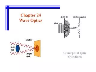
Diffraction of light: X X • S Y Y The phenomenon of bending of light around the corners and the encroachment of light within the geometrical shadow of the opaque obstacles is called diffraction. • S Slit Obstacle Screen Diffraction at a slit Diffraction at an obstacle Screen X & Y – Region of diffraction
A • • • • • • d • • • • • • • D B Diffraction of light at a single slit: 1) At an angle of diffractionθ = 0°: θ = 0° 0 1 2 3 4 5 6 7 8 9 10 11 12 • Bright O Plane Wavefront Slit Screen The wavelets from the single wavefront reach the centre O on the screen in same phase and hence interfere constructively to give Central or Primary Maximum (Bright fringe).
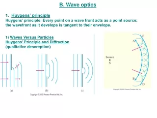
θ1 A • • • • • • θ1 • • λ/2 • • • • θ1 • λ B Plane Wavefront Slit Screen 2) At an angle of diffractionθ = θ1: The slit is imagined to be divided into 2 equal halves. 0 1 2 3 4 5 6 7 8 9 10 11 12 • Dark P1 • Bright O N The wavelets from the single wavefront diffract at an angle θ1 such that BN is λ and reach the point P1. The pairs (0,6), (1,7), (2,8), (3,9), (4,10), (5,11) and (6,12) interfere destructively with path difference λ/2 and give First Secondary Minimum (Dark fringe).
3) At an angle of diffractionθ = θ2: • P1’ • P2 A θ2 • 0 1 2 3 4 5 6 7 8 9 10 11 12 • • • P1 • • λ/2 • θ2 • • O • λ • • 3λ/2 • N Plane Wavefront • θ2 Slit • 2λ B Screen The slit is imagined to be divided into 4 equal parts. Dark Dark Bright The wavelets from the single wavefront diffract at an angle θ2 such that BN is 2λ and reach the point P2. The pairs (0,3), (1,4), (2,5), (3,6),(4,7), (5,8), (6,9), (7,10), (8,11) and (9,12) interfere destructively with path difference λ/2 and give Second Secondary Minimum (Dark fringe).
• P2 • θ1’ P1’ A • 0 1 2 3 4 5 6 7 8 9 10 11 12 • • • P1 • • • λ/2 θ1’ • • O • • λ • • • θ1’ N Plane Wavefront • Slit B 3λ/2 Screen 4) At an angle of diffractionθ = θ1’: The slit is imagined to be divided into 3 equal parts. Bright Dark Bright The wavelets from the single wavefront diffract at an angle θ1’ such that BN is 3λ/2 and reach the point P1’.The pairs (0,8), (1,9), (2,10), (3,11) and(4,12) interfere constructively with path difference λ and (0,4), (1,5), (2,6), …… and (8,12) interfere destructively with path difference λ/2.However due to a few wavelets interfering constructively First Secondary Maximum (Bright fringe) is formed.
• P2 • P2 • θ = 0 P1’ A θ1 A • • θ1’ P1’ • 0 1 2 3 4 5 6 7 8 9 10 11 12 A • 0 1 2 3 4 5 6 7 8 9 10 11 12 • • • A θ2 • 0 1 2 3 4 5 6 7 8 9 10 11 12 • • • P1 • 0 1 2 3 4 5 6 7 8 9 10 11 12 • • • • P1 • • • • • P1 • • • • • θ1 • O • • • λ/2 • O • λ/2 θ1’ • • • • O • θ2 λ/2 • • • • O • • • • λ • λ • • • • • • • N • 3λ/2 θ1 • • • B θ1’ N N Plane Wavefront Plane Wavefront Plane Wavefront Plane Wavefront • λ • B θ2 Slit Slit Slit Slit • B 3λ/2 2λ B Screen Screen Screen Screen Diffraction at various angles: θ2 θ1’ θ1 θ = 0 I Central Maximum is the brightest fringe. Diffraction is not visible after a few order of diffraction.
Theory: The path difference between the 0th wavelet and 12th wavelet is BN. If ‘θ’ is the angle of diffraction and ‘d’ is the slit width, then BN = d sin θ To establish the condition for secondary minima, the slit is divided into 2, 4, 6, … equal parts such that corresponding wavelets from successive regions interfere with path difference of λ/2. Or for nth secondary minimum, the slit can be divided into 2n equal parts. For θ1, d sin θ1 = λ For θ2, d sin θ2 = 2λ For θn, d sin θn = nλ Since θn is very small, d θn = nλ θn = nλ / d (n = 1, 2, 3, ……) To establish the condition for secondary maxima, the slit is divided into 3, 5, 7, … equal parts such that corresponding wavelets from alternate regions interfere with path difference of λ. Or for nth secondary minimum, the slit can be divided into (2n + 1) equal parts. For θ1’, d sin θ1’ = 3λ/2 For θ2’, d sin θ2’ = 5λ/2 For θn’, d sin θn’ = (2n + 1)λ/2 Since θn’ is very small, d θn’ = (2n + 1)λ / 2 θn’ = (2n + 1)λ / 2d (n = 1, 2, 3, ……)
θ1 A • 0 1 2 3 4 5 6 7 8 9 10 11 12 • • • P1 • • • θ1 • • O • λ/2 • • • • N θ1 • Plane Wavefront λ B Slit Screen Width of Central Maximum: Dark y1 d Bright D tan θ1 = y1 / D or θ1 = y1 / D(since θ1 is very small) d sin θ1 = λ orθ1 = λ / d(since θ1 is very small) y1 = D λ / d Since the Central Maximum is spread on either side of O, the width is β0 = 2D λ / d
Fresnel’s Distance: Fresnel’s distance is that distance from the slit at which the spreading of light due to diffraction becomes equal to the size of the slit. y1 = D λ / d At Fresnel’s distance, y1 = d and D = DF So, DFλ / d = d or DF = d2 / λ If the distance D between the slit and the screen is less than Fresnel’s distance DF, then the diffraction effects may be regarded as absent. So, ray optics may be regarded as a limiting case of wave optics. Difference between Interference and Diffraction:
Polarisation of Transverse Mechanical Waves: 90° Narrow Slit Transverse disturbance (up and down) Narrow Slit Transverse disturbance (up and down) Narrow Slit
Polarisation of Light Waves: Wave • • • • • • • • • • S - Parallel to the plane • • - Perpendicular to the plane Natural Light Representation of Natural Light In natural light, millions of transverse vibrations occur in all the directions perpendicular to the direction of propagation of wave. But for convenience, we can assume the rectangular components of the vibrations with one component lying on theplane of the diagram and the other perpendicular to the plane of the diagram.
Optic Axis • • • • • • • • • • • • 90° Light waves are electromagnetic waves with electric and magnetic fields oscillating at right angles to each other and also to the direction of propagation of wave.Therefore, the light waves can be polarised. Unpolarised light Plane Polarised light Plane Polarised light Polariser Tourmaline Crystal Analyser Tourmaline Crystal No light Plane Polarised light Unpolarised light
90° • • • • • • Plane of Vibration Plane of Polarisation Unpolarised light Plane Polarised light Polariser Analyser When unpolarised light is incident on the polariser, the vibrations parallel to the crystallographic axis are transmitted and those perpendicular to the axis are absorbed. Therefore the transmitted light is plane (linearly) polarised. The plane which contains the crystallographic axis and vibrations transmitted from the polariser is called plane of vibration. The plane which is perpendicular to the plane of vibration is called plane of polarisation.
Malus’ Law: a a sin θ a cos θ P A θ When a beam of plane polarised light is incident on an analyser, the intensity I of light transmitted from the analyser varies directly as the square of the cosine of the angle θ between the planes of transmission of analyser and polariser. I α cos2θ If a be the amplitude of the electric vector transmitted by the polariser, then only the component a cos θ will be transmitted by the analyser. Intensity of transmitted light from the analyser is Case I : When θ = 0° or 180°, I = I0 Case II : When θ = 90°, I = 0 Case III: When unpolarised light is incident on the analyser the intensity of the transmitted light is one-half of the intensity of incident light.(Since average value of cos2θ is ½) I = k (a cos θ)2 or I = k a2 cos2θ I = I0 cos2θ (where I0 = k a2 is the intensity of light transmitted from the polariser)
• • • • • • • • • • • • 90° r sin θP aμb = sin r sin θP aμb = sin 90° - θP Polarisation by Reflection and Brewster’s Law: The incident light wave is made of parallel vibrations (π – components) on the plane of incidence and perpendicular vibrations (σ – components : perpendicular to plane of incidence). a θP μ At a particular angle θP, the parallel components completely refracted whereas the perpendicular components partially get refracted and partially get reflected. i.e. the reflected components are all in perpendicular plane of vibration and hence plane polarised. The intensity of transmitted light through the medium is greater than that of plane polarised (reflected) light. b θP + r = 90° or r = 90° - θP aμb = tan θP
Polaroids: H – Polaroid is prepared by taking a sheet of polyvinyl alcohol (long chain polymer molecules) and subjecting to a large strain. The molecules are oriented parallel to the strain and the material becomes doubly refracting. When strained with iodine, the material behaves like a dichroic crystal. K – Polaroid is prepared by heating a stretched polyvinyl alcohol film in the presence of HCl (an active dehydrating catalyst). When the film becomes slightly darkened, it behaves like a strong dichroic crystal. Uses of Polaroids: • Polaroid Sun Glasses • Polaroid Filters • For Laboratory Purpose • In Head-light of Automobiles • In Three – Dimensional Motion Picutres • In Window Panes • In Wind Shield in Automobiles End of Wave Optics