Lab 1 - Microcontrollers
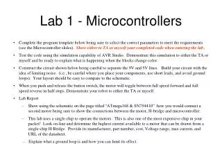
Lab 1 - Microcontrollers. Complete the program template below being sure to select the correct parameters to meet the requirements (see the Microcontroller slides). Show either to TA or myself your completed code when entering the lab .

Lab 1 - Microcontrollers
E N D
Presentation Transcript
Lab 1 - Microcontrollers • Complete the program template below being sure to select the correct parameters to meet the requirements (see the Microcontroller slides). Show either to TA or myself your completed code when entering the lab. • Test the code using the simulation capability of AVR Studio. Demonstrate this simulation to either the TA or myself and be ready to explain what is happening when the blocks change color. • Construct the circuit shown below being careful to separate the 9V and 5V lines. Build your circuit with the idea of limiting noise. (i.e., be careful where you place your components, use short leads, and avoid ground loops). Your layout should be easy to compare to the schematic. • When you push and release the button switch, the motor will toggle between full speed forward and full speed reverse in half steps. Demonstrate your robot to either the TA or myself. • Lab Report • Show using the schematic on the page titled “ATmega168 & SN754410” how you would connect a second motor being sure to show the connections between the motor, H-bridge and microcontroller. • This lab uses a single chip to operate the motors. This is also one of the most expensive chip in your packet! Look on-line and determine the highest current available to a motor that can be drawn from a single-chip H-Bridge. Provide its manufacturer, part number, cost, Voltage range, max current, and URL of the datasheet. • Explain what a ground loop is and how you can limit its effect.
Voltage Regulator5V for microcontroller circuit Note: The capacitor values in your kits may be different. Place your capacitors in the optimum positions. 7805 From 9V battery Or battery pack +7 VDC to +20 VDC Unregulated input D1 1N5817 (Schottky) Regulated Output Ground To Robot Circuits +5 VDC C1 100F C2 0.1F +
ATmega168 & SN754410Microcontroller Connections for H-Bridge Driver
Suggested Breadboard Layout HBeat VR H-Bridge Button LCD
Code for Microcontroller LabAdd motor routine #define LEFT_MOTOR 1 void motor( int mtr, int speed) { static int fwd; static int rev; if (speed > 0) { fwd = speed; rev = 0; } else if (speed<0) { fwd = 0; rev = -speed; } else { fwd = 0; rev = 0; } if (mtr == LEFT_MOTOR) { OCR?A = fwd; OCR?B = rev; } }
Add interrupt routine • ISR( External Interrupt Vector ?) • { static int dutycycle = 0; • unsigned char x; • x = PINB & 0b00010000; //Note the use of the mask. What values can x have? • if (x==0) // What position is the button in to get x = 0? • { • dutycycle += 1; • if (dutycycle > 7) • dutycycle = 0; • switch (dutycycle) • { • case 0: • motor(LEFT_MOTOR, ? ); //Off • break; • case 1: • motor(LEFT_MOTOR, ? ); //50% Forward • break; • case 2: • motor(LEFT_MOTOR, ? ); //100% Forward • break; • case 3: • motor(LEFT_MOTOR, ? ); //50% Forward • break; • case 4: • motor(LEFT_MOTOR, ? ); //Off • break; • case 5: • motor(LEFT_MOTOR, ? ); //50% Reverse • break; • case 6: • motor(LEFT_MOTOR, ? ); //100% Reverse • break; • case 7: • motor(LEFT_MOTOR, ? ); //50% Reverse • break; • } • printf(“DC: %d \n”, dutycycle); // Note the use of \n • } • }
Code for Microcontroller LabAdd to main routine int main (void) { … /* Left Motor */ //Setup the PWM on pin 17 (PB3) TCCR?A = ? ; // Setup for 0 Volts when counter is low; Phase Correct PWM TCCR?B = ? ; // Use an 8-bit prescaler OCR?A = ?; // Initialize motor so that it is off DDRB = ? ; // Don’t forget to set this pin as an output //Setup the PWM on pin 5 (PD3) TCCR?A = ? ; // Setup for 0 Volts when counter is low; Phase Correct PWM OCR?B = ? ; // Initialize motor so that it is off DDRD |=? ; // Don’t forget to set this pin as an output … }