Download
1 / 21
260 likes | 486 Vues
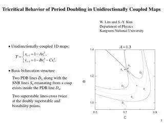
EVALUATION OF COUPLED SHEAR-FLOW BEHAVIOR OF SINGLE ROCK JOINTS. R. Saho, Y. Jiang, Y.Tanabashi, B.Li. Graduate School of science and technology Nagasaki University. Background of research.

E N D
EVALUATION OF COUPLED SHEAR-FLOW BEHAVIOR OF SINGLE ROCK JOINTS R. Saho, Y. Jiang, Y.Tanabashi, B.Li Graduate School of science and technologyNagasaki University
Background of research In recent years, the development of deep underground spaces like radioactive waste disposal has received great attention in all countries operating nuclear power plants. Geological disposal is the most promising option for a safe long-term management of radioactive waste as agreed by scientists and politicians. These facilities positively utilize the isolability and impermeability of rock masses,which require the thoroughly understanding of the mechanical-hydraulic behaviors of rock fractures in rock mass.
Background Schematic cross-action of Yucca Mountain (America) and depiction of processes that are important to repository performance
Purpose of research Shear-flow coupling test Fluid flow in rock mass takes places predominantly through fractures. ・A fracture normally undergoes stresses from two directions, normal stress and shear stress. ・The void structures in the fracture change remarkably due to dilation and the relative displacement between the two joint walls especially for mated joints. Understanding the permeability property of rock fractures in shear process.
A new direct shear-flow test apparatus (1) The shearing process could be applied on single rock joint under either CNL or CNS boundary conditions with the hydraulic tests at the same time. (2) The weight of water flowing out of the fracture is measured by an electrical balance in real time.
A new direct shear-flow test apparatus Differential manometer measurement (3) The water head can be accurately measured by using a differential manometer.
A new direct shear-flow test apparatus PC Digital Camera Water Tank Acrylic board Shear load Joint surface Normal load (4) Visualization system for shear-flow test of rock joints.
Test on parallel-plate model A typical fracture contains isolated asperity regions where the two rock surface are in contact,surrounded by open regions where the two surface are separated by an aperture that may vary from point to point. A simple parallel- plates model was used in hydraulic tests by changing the arrangement and ratio of contact areas. The setting contact areas on two smooth parallel plates with uniform aperture,by changing the distribution case (case 1, case 2, case 3) and contact ratio (15%, 20%, 25%) to test the response of flow to the contacts. aperture 0.07mm,0.14mm,0.21mm,0.28mm, 0.35mm Water head (h) 2.0m, 1.0m,0.5m
Methodology to evaluate the hydraulic conductivity flow e w L If considering the joint as composed of two smooth parallel plates and the flow to be steady, single phase, laminar and incompressible, the Darcy’s law may be written as: Where is usually called the “cubic law” Q: the volumetric flow g: the acceleration of gravity e: the hydraulic aperture n: the kinematic viscosity of the fluid i: the hydraulic gradient Cubic law is exact only for smooth-wall fractures with uniform aperture.
Experiment case Contact ratio 15% 20% 25% case 1 2 3 (Contact area: )
Test results (Contact area20%) Cubic law deviation Experimental results distribute below the Cubic law h=1.0m h=2.0m h=0.5m A part of flow may have changed from the laminar flow to turbulent flow at large mechanical apertures.
Test results of different arrangements(Contact area20%) Similar tendency Cubic law Case 1 Case 2 Case 3 Case 1 Case 2 Case 3 The arrangement of contact areas seems to have negligible influence on the flow through a fracture.
Test result of different contact ratios Cubic law 20% 25% Contact ratio= contact area/fracture area 15% 15% 20% 25% Contact ratio have significant influence on the flow through a fracture.
Surface view of specimen Joint 1 Joint 2 Three shear-flow tests were carried out with boundary conditions: case 1: CNL(1) normal stress s n0=1MPa case 2: CNL(2) normal stress s n0=2MPa case 3: CNS normal stress s n0=1MPa , normal stiffness kn=0.5GPa/m
Shear behaviours of rock joint Peak shear stress Residual strength CNL(σn0=1MPa) CNL(σn0=2MPa) CNS(σn0=1MPa kn=0.5GPa/m) Joint 2 Joint 1 Larger shear stresses are obtained under either higher normal stress or higher normal stiffness at the same initial normal stress.
Normal behaviours of rock joint CNL(σn0=1MPa) CNL(σn0=2MPa) CNS(σn0=1MPa kn=0.5GPa/m) Joint 2 Joint 1 Relation between shear displacement and normal displacement. Positive dilation is shown in the residual region and negative dilation is generated when a shear starts.
Conductivity versus sheardisplacement (CNL:σn0=2MPa) High hydraulic gradient Middle hydraulic gradient Low hydraulic gradient Average of hydraulic gradient Joint 1 Joint 2 The conductivity decreases as hydraulic gradient increase. The values of the conductivities are greatly different.
Comparison of hydraulic aperture andmechanical aperture (CNL:σn0=2MPa) Hydraulic aperture Mechanical aperture Joint 1 Joint 2 In the initial stage of shear, the apertures decrease remarkably and then increase as shearing. The mechanical aperture and hydraulic aperture agrees well with each other.
Conclusions A newly-developed shear-flow test apparatus was used to carry out the tests on parallel-plate model and artificial rock joints. (1) The contact ratio has a greater influence on the fluid flow than the arrangement of contact area. (2) The rock joint dilates as the shear displacement progresses as well as the mechanical and hydraulic aperture. (3) Higher shear stress and dilation value could be obtained on a joint with greater roughness.
Future study (1) More shapes of contact area will be tested based on the parallel-plates model in the future study as well as improving the precise of the test apparatus. (2) Shear-flow coupling tests are required on more abundant rock fractures with different sizes under various boundary conditions. (3) Visual tracer test will be developed to find out more detailed information of the fluid flow though a rock fracture.
安 全 第 一 謝謝 Theend