Understanding Jet Engine Operation: Mechanisms of Airflow, Compression, Combustion, and Thrust
90 likes | 230 Vues
This overview explains the fundamental operations of a jet engine, detailing how air intake, compression, and combustion generate thrust. The engine draws in air through its front intake, compresses it, and mixes it with fuel in the combustion chamber, creating high-temperature gases. These gases expand and exit through the rear, pumping energy back into the turbine, which powers the compressor. The article breaks down the key processes of 'suck', 'squeeze', 'bang', and 'blow' involved in thrust generation, emphasizing the intricate engineering behind modern jet engines.

Understanding Jet Engine Operation: Mechanisms of Airflow, Compression, Combustion, and Thrust
E N D
Presentation Transcript
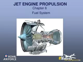
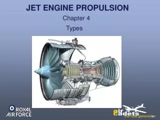
The image above shows how a jet engine would be situated in a modern military aircraft. In the basic jet engine, air enters the front intake and is compressed (we will see how later). Then the air is forced into combustion chambers where fuel is sprayed into it, and the mixture of air and fuel is ignited. Gases that form expand rapidly and are exhausted through the rear of the combustion chambers. These gases exert equal force in all directions, providing forward thrust as they escape to the rear. As the gases leave the engine, they pass through a fan-like set of blades (turbine), which rotates a shaft called the turbine shaft. This shaft, in turn, rotates the compressor, thereby bringing in a fresh supply of air through the intake. Below is an animation of an isolated jet engine, which illustrates the process of air inflow, compression, combustion, air outflow and shaft rotation just described.
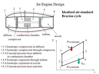
The process can be described by the following diagram adopted from the website of Rolls Royce, a popular manufacturer of jet engines. • This process is the essence of how jet engines work, but how exactly does something like compression (squeezing) occur? To find out more about each of the four steps in the creation of thrust by a jet engine, see below.
SUCKThe engine sucks in a large volume of air through the fan and compressor stages. A typical commercial jet engine takes in 1.2 tons of air per second during takeoff—in other words, it could empty the air in a squash court in less than a second. The mechanism by which a jet engine sucks in the air is largely a part of the compression stage. In many engines the compressor is responsible for both sucking in the air and compressing it. Some engines have an additional fan that is not part of the compressor to draw additional air into the system. The fan is the leftmost component of the engine illustrated above. • SQUEEZEAside from drawing air into the engine, the compressor also pressurizes the air and delivers it to the combustion chamber. The compressor is shown in the above image just to the left of the fire in the combustion chamber and to the right of the fan. The compression fans are driven from the turbine by a shaft (the turbine is in turn driven by the air that is leaving the engine). Compressors can achieve compression ratios in excess of 40:1, which means that the pressure of the air at the end of the compressor is over 40 times that of the air that enters the compressor. At full power the blades of a typical commercial jet compressor rotate at 1000mph (1600kph) and take in 2600lb (1200kg) of air per second.
Now we will discuss how the compressor actually compresses the air. • As can be seen in the image above, the green fans that compose the compressor gradually get smaller and smaller, as does the cavity through which the air must travel. The air must continue moving to the right, toward the combustion chambers of the engine, since the fans are spinning and pushing the air in that direction. The result is a given amount of air moving from a larger space to a smaller one, and thus increasing in pressure. • BANGIn the combustion chamber, fuel is mixed with air to produce the bang, which is responsible for the expansion that forces the air into the turbine. Inside the typical commercial jet engine, the fuel burns in the combustion chamber at up to 2000 degrees Celsius. The temperature at which metals in this part of the engine start to melt is 1300 degrees Celsius, so advanced cooling techniques must be used. • The combustion chamber has the difficult task of burning large quantities of fuel, supplied through fuel spray nozzles, with extensive volumes of air, supplied by the compressor, and releasing the resulting heat in such a manner that the air is expanded and accelerated to give a smooth stream of uniformly heated gas. This task must be accomplished with the minimum loss in pressure and with the maximum heat release within the limited space available.
The amount of fuel added to the air will depend upon the temperature rise required. However, the maximum temperature is limited to certain range dictated by the materials from which the turbine blades and nozzles are made. The air has already been heated to between 200 and 550 °C by the work done in the compressor, giving a temperature rise requirement of around 650 to 1150 °C from the combustion process. Since the gas temperature determines the engine thrust, the combustion chamber must be capable of maintaining stable and efficient combustion over a wide range of engine operating conditions. • The air brought in by the fan that does not go through the core of the engine and is thus not used for combustion, which amounts to about 60 percent of the total airflow, is introduced progressively into the flame tube to lower the temperature inside the combustor and cool the walls of the flame tube.
BLOWThe reaction of the expanded gas—the mixture of fuel and air—being forced through the turbine, drives the fan and compressor and blows out of the exhaust nozzle providing the thrust. • Thus, the turbine has the task of providing power to drive the compressor and accessories. It does this by extracting energy from the hot gases released from the combustion system and expanding them to a lower pressure and temperature. The continuous flow of gas to which the turbine is exposed may enter the turbine at a temperature between 850 and 1700 °C, which is again far above the melting point of current materials technology. • To produce the driving torque, the turbine may consist of several stages, each employing one row of moving blades and one row of stationary guide vanes to direct the air as desired onto the blades. The number of stages depends on the relationship between the power required from the gas flow, the rotational speed at which it must be produced, and the diameter of turbine permitted.
The desire to produce a high engine efficiency demands a high turbine inlet temperature, but this causes problems as the turbine blades would be required to perform and survive long operating periods at temperatures above their melting point. These blades, while glowing red-hot, must be strong enough to carry the centrifugal loads due to rotation at high speed.To operate under these conditions, cool air is forced out of many small holes in the blade. This air remains close to the blade, preventing it from melting, but not detracting significantly from the engine's overall performance. Nickel alloys are used to construct the turbine blades and the nozzle guide vanes because these materials demonstrate good properties at high temperatures