Download
1 / 15
150 likes | 273 Vues
UNIVERSITY OF PUERTO RICO AT HUMACO DEPARTMENT OF PHYSICS ENGINEERING GRAPHICS I Sketching Dr. Walter L ópez Moreno. Line Conventions. Visible Lines – solid thick lines that represent visible edges or contours Hidden Lines – short evenly spaced dashes that depict hidden features

E N D
UNIVERSITY OF PUERTO RICO AT HUMACO DEPARTMENT OF PHYSICS ENGINEERING GRAPHICS I Sketching Dr. Walter López Moreno
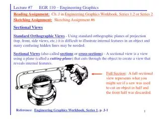
Line Conventions Visible Lines – solid thick lines that represent visible edges or contours Hidden Lines – short evenly spaced dashes that depict hidden features Section Lines – solid thin lines that indicate cut surfaces Center Lines – alternating long and short dashes Dimensioning Dimension Lines - solid thin lines showing dimension extent/direction Extension Lines - solid thin lines showing point or line to which dimension applies Leaders – direct notes, dimensions, symbols, part numbers, etc. to features on drawing Cutting-Plane and Viewing-Plane Lines – indicate location of cutting planes for sectional views and the viewing position for removed partial views Break Lines – indicate only portion of object is drawn. May be random “squiggled” line or thin dashes joined by zigzags. Phantom Lines – long thin dashes separated by pairs of short dashes indicate alternate positions of moving parts, adjacent position of related parts and repeated detail Chain Line – Lines or surfaces with special requirements
Viewing-plane line 1 Dimension Line 4 Center Line 3 Extension line 2 Hidden Line 5 6 Break Line Cutting-plane Line 7 8 Visible Line Center Line (of motion) 9 10 Leader Phantom Line 14 13 Section Line 11 VIEW B-B 12 SECTION A-A Source: http://www.genium.com/pdf/dmpc.pdf
Lettering Plain Gothic Italics are OK ABCDEFGHIJKLMNOPQRSTUVWXYZ abcdefghijklmnopqrstuvwxyz
Sketching Drawings made without mechanical drawing tools Free-Hand Ruler Simple drawing program Should follow standards and conventions From Course Text
Pictorial 3-dimensional representations One-point one vanishing point lines that are not vertical or horizontal converge to single point in distance Two-point or Three-point two or three vanishing points With two points, vertical orhorizontal lines parallel, but not both With three-point, no lines are parallel Isometric Drawing shows corner of object, but parallel lines on object are parallel in drawing Shows three dimensions, but no vanishing point(s) Source: “Introduction to Engineering”, by Paul Wright
One-point Two-Point Source: “Introduction to Engineering”, by Paul Wright
Isometric From Course Text
Orthographic / Multiview Draw object from two / three perpendicular views What it looks like pictorially / Orthographic From Course Text
Top view Front View
Section Views If three views are not enough, draw sections needed to completely describe the object. Section A-A View B-B
Auxiliary Views Used to show true dimensions of an inclined plane. Source: “Introduction to Engineering”, by Paul Wright
Battery Cell Variable Resistor Resistor Connecting wire Motor Switch (open or closed) Light Emitting Diode (LED) Ammeter Lamp in holder Buzzer Junction between conductors Electrical Circuit Symbols For good websites with more symbols, type “Schematic Symbols” into a web search engine. Source: http://www.cleapss.org.uk/
Chemical Process Block Diagram Online module on block diagrams From Course Text
REFERENCE: Taken from “Introduction to Engineering”, by Paul Wright 2009