Multiview Sketches
Multiview Sketches. Engineering Graphics Stephen W. Crown Ph.D. Objective. How to use sketching as an effective tool in the engineering design process How to represent a 3-D object effectively on a 2-D drawing surface (multiview sketching). Overview. Sketching Definition


Multiview Sketches
E N D
Presentation Transcript
Multiview Sketches Engineering Graphics Stephen W. Crown Ph.D.
Objective • How to use sketching as an effective tool in the engineering design process • How to represent a 3-D object effectively on a 2-D drawing surface (multiview sketching)
Overview • Sketching • Definition • Tools / Instruments • Mechanics of sketching • Lines and Curves • A Bounding Box • Multiview sketches • How to create them • When to use them • Why use sketches? • Creativity • Communication • Documentation
Sketching • Definition: A rough freehand drawing used to document, communicate, and refine ideas developed in the ideation phase of the design process • Beginners will benefit from instruments • Follows standard practices • A developed skill • Should be the first step of any CAD drawing
Tools • Pencils • Use a mechanical pencil (0.5mm lead) • Practice using different pressure to produce desired linetypes (construction lines) • Paper • Unlined paper is the most useful • Square grid and tracing paper is often useful • Eraser • A good eraser is worth the investment • Do not overuse your eraser (save some mistakes)
Using Simple Instruments • The use of mechanical instruments is recommended only for beginners. Break away from reliance on tools that slow you down. • Helpful tools for beginners • Compass • Triangles • Dividers • Ruler
Mechanics of Sketching • Drawing straight lines • Drawing curved lines • Using a bounding box
Drawing straight lines • Mark starting and ending point • Break long lines into short line segments by marking the midpoint • Start with a light pass if necessary and then darken • Use a loose comfortable grip • Reorient the paper to your convenience • test your skill with different orientations • an awkward orientation may occasionally produce positive results
Drawing curved lines • Break large arcs/circles into small segments • Make guide marks for each segment • Circles and Ellipses • Sketch a light square/rectangle • Lightly sketch in diagonals • Mark contact points on square/rectangle • Rotate the paper for each segment
Bounding Box and Construction Lines • Plan • choose proper scale and orientation • don’t crowd sketches • Start with a bounding box • Use light straight construction lines • Draw boundary lines of internal features starting with the largest features • Sketch dark object lines using light boundary lines as a guide
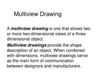
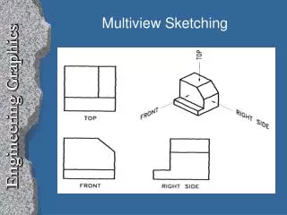
Multiview Sketching • Represents a 3-D object with a series of 2-D views in contrast to “pictorials” which show all three dimensions in a single view • Also called orthographic projection • Best understood by engineers or technically trained people Multiview Drawing Pictorial
Parallel projection • Preserves true relationship between features • The geometry is generally not distorted • Lines that are parallel on the object are parallel on the drawing • Parallel projectors • The object is projected onto a projection plane as a shadow is projected where the rays form the light source are parallel. • Projection from one view to another is accomplished with parallel projection lines
Parallel versus Perspective Projection Parallel Parallel Perspective Perspective
Projection Planes versus Views • Projection planes: • Object formed from projection lines projected perpendicularly onto a projection plane • Planes: Horizontal, frontal, and profile • Each projection plane is perpendicular to adjacent projection planes • Principle views • The object is rotated 90 degrees about the horizontal or vertical axis to give six principle views (top, bottom, front, rear, left, and right side) • Common views: top, front, and right side
Only use Necessary Views • One view drawings • Stamped, thin or extruded parts • Specify thickness with a note • Two view drawings • Cylindrical parts • Show the circular and rectangular view • Three view drawings • Usually sufficient for all other drawings • Top, front, and right side view
Orientation and Placement of Views • The most descriptive view should be selected as the front view • The natural orientation of the part should be preserved if possible • Views must be aligned • Top view above front view • Right view to the right of front view
Hidden lines • Represented with dashed lines • Precedence of lines (visible, hidden, center) • Views should be selected to minimize the use of hidden lines most descriptive view should be selected as the front view
First Versus Third Angle Projection • Third Angle Projection Associated with English units • First Angle Projection Associated with SI units ANSI Symbol
Fold Lines • Represents a 90 degree fold between views • Generally not shown on engineering drawings except when views other than the principle views (auxiliary views) are used. • Labeled as: H/F, F/P, F/1, 1/2
Terminology to Relate Views • Adjacent view • A view that is separated by a fold line • The top view is an adjacent view to the front view • Central View • A view that is between two adjacent views • The front view is the central view of the top, front, and right side view • Related views • Two views that are adjacent to a central view • The top and right side view are related views since they are both adjacent to the front view
Constructing a New View 2 • The top and front views of a surface are shown • The fold line represents a 90 degree fold between the views • Parallel projection lines are perpendicular to the fold line 1 3 1 3 2
2 1 3 1 1 3 3 2 2 Constructing a New View • A vertical fold line is drawn at an arbitrary distance from the front view • Parallel projection lines are drawn from each vertex • The common depth between the top and side view is used to locate each vertex on the projection lines
Sketching as Part of the Creative Design Process • Quickly translate thoughts to paper • An effective means of communication • Stimulates creativity and visualization
Sketching Allows for the Quick Translation of Thoughts to Paper • Commit thoughts to paper before you lose an idea • Avoid the of use mechanical tools (drawing tools are helpful for beginners) • Does not need to be an exact representation • objects may be simplified • parts may be missing • Avoid erasing • as new ideas are developed make new sketches • start with light lines and then darken with darker lead or heavier strokes
Sketching is An Effective Means of Communication • Understand your audience • Who is looking at the sketches? • What details are they interested in? • What type of sketch will they best understand? • Follow standard practices • You may not always accompany your sketches • Others may misinterpret your drawing • Sketches provide a log of ideas that were considered in a brainstorming session
Sketching Stimulates Creativity and Helps Visualization • The process of sketching ideas that are partially developed often aids the design process • do not wait until you have a clear picture before you start sketching • allow yourself the freedom to make mistakes • Visualization of the entire design is essential but often impossible without aid of sketches
Appendix Engineering Graphics
Make a Quick Sketch • You will have ten seconds to make a sketch of each object shown below before being asked a few questions about the objects. • How many of the nine views consisted of a square bounding box? • How many of the nine views are the same? • How many of the nine views consisted of only vertical or horizontal lines? • What is the volume of each object (Cube=8 in3)?