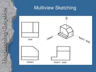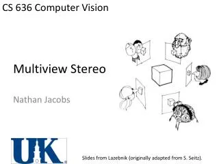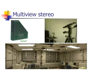
Multiview Projection
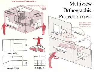
This method illustrates obtaining multiview projections by using transparent planes and projectors to show front, top, and right-side views of objects. The Glass Box Method demonstrates aligning six principal views on a flat sheet using folding lines. The procedure includes transferring depth dimensions with a 45-degree miter line between the top and side views.

Multiview Projection
E N D
Presentation Transcript
Multiview Projection Multiview Projection
Multiview Projection The method of viewing an object to obtain a multiview projection is illustrated in figure a. Between the observer and the object a transparent plane is located parallel to the front view. The view is obtained by drawing perpendicular lines (projectors) from all points of the edges of the object to the plane of projection (figure b). The piercing points of these projectors form lines on the projection plane (figure c)
Multiview Projection A similar procedure can be used to obtain the top view (figure a) and the right-side view (figure b).
Multiview Projection If planes of projection are placed parallel to the principal faces of the object, they for a “glass box” as shown in figure a. Since the glass box has six sides, six views of the object can be obtained. To show the views on a flat sheet of paper it is necessary to unfold the planes so that they will all lie in the same plane. All planes except the rear plane are hinged to the frontal plane (figure b).
Multiview Projection The positions of the six planes after they have been revolved are shown.
Multiview Projection The front, top, and right-side views of the object are shown with folding lines between the views. These folding lines correspond to the hinge lines of the glass box (figure a). The H/F folding line is between the top and front views. The F/P folding line is between the front and right-side views. Folding lines are useful in solving graphical problems in descriptive geometry. As a rule folding lines are omitted in industrial practice (figure b).
The Glass Box Method of Projection The Glass Box: Alignment of the six principal views
The Glass Box Method of Projection The Glass Box: Planes of Projection Frontal plane of projection – the plane upon which the front view is projected. Horizontal plane of projection – the plane upon which the top view is projected. Profile plane of projection – the plane upon which the side view is projected.
The Glass Box Method of Projection The Glass Box: Fold Lines Fold lines are imaginary lines separating the planes of projection corresponding to the hinged lines of the glass box.
The Glass Box Method of Projection Transferring Depth Dimensions A 45 degree miter-line is used to project the Depth dimension between the Top view and the Side view.