Engine Nacelle Halon Replacement
370 likes | 406 Vues
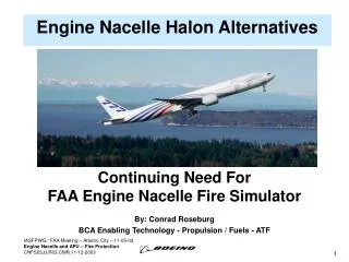
This presentation explores transitioning from Halon 1301 to HFC-125 in Nacelle Fire Simulator systems, discussing qualitative and quantitative research outcomes, thermal characterization, and suppressing negative impacts.

Engine Nacelle Halon Replacement
E N D
Presentation Transcript
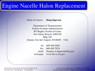
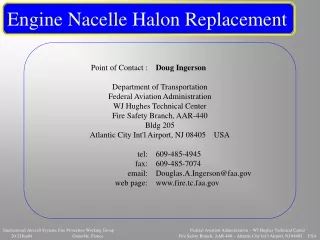
Engine Nacelle Halon Replacement International Aircraft Systems Fire Protection Working Group Douglas Ingerson, Engineer Federal Aviation Administration WJ Hughes Technical Center Fire Safety Team Atlantic City Int’l Airport, NJ USA tel : 609-485-4945 email : douglas.a.ingerson@faa.gov 17Nov2009
Presentation OverviewMajor Discussion Points • The “MPSe rev03 to rev04” Transition • Overview & Status • Flow Visualization in a Small-Scale Wind Tunnel • Work accomplished for qualitative purpose • Providing pictures of tube array & fuel pan lip wake regions • Gas Analysis in the Nacelle Fire Simulator • Work accomplished for quantitative purpose • Outcomes show a certain MPSe modification is permissible • Thermal Characterization of the NFS Fires • Test fixture modifications underway • Providing pictures & brief description
MPSe Rev 03 04, Overview • Issues driving the test process revision • Terminating the use of halon 1301 in the test process • General characteristics for halon-replacing fire suppressants are becoming more unlike halon 1301 • Fire suppressants are becoming more like “streaming” agents, as indicated by the trend of increasing normal boiling points • Liquid & solid aerosols appear to offer solutions • Must degrade confusing effects occurring during the assessment of an “equivalent” amount of a fire suppressant in a nacelle fire simulator (NFS)
MPSe Rev 03 04, OverviewTerminating Halon 1301 Usage • Modify the halon 1301 benchmark process • A surrogate will replicate the flame extinction behavior of halon 1301 for certain test conditions • Surrogate = HFC-125 • Thermally characterize fire threats • Benchmark process may be dropped in the future • Energy release will be measured “globally” via a “control volume” while invoking symmetry logic • Air-sensing thermocouples • “Heat flux” plates
MPSe Rev 03 04, OverviewDegrading the Negative Impacts on Assessment • Modify test process • Change from an iterative search to a proof-test • Requires preliminary testing to produce an identified suppressant delivery for the 2 NFS ventilation conditions • Review suppressant measurement rationale • Investigate with flow testing at small- & large-scale • Perhaps revise measurement concept when considering : • Trends for the characteristics of halon-replacing fire suppressants • MPSe rev03 based solely on free-stream measurement • Wake region measurement provides a “total-flood” challenge • Rev04 plan to incorporate some wake region measurements • Outcomes from flow observations
MPSe Rev 03 04, Status • Items Completed • Small-scale flow visualizations • Large-scale flow observations • Remaining tasks are in-process • HFC-125 surrogate validation; testing begins momentarily • Modify test fixture for thermal characterization; underway • Administrative considerations for MPSe rev04; underway • Altering test process flow • Define additional alterations based on flow observation outcomes • Define surrogate benchmark processes • Author the draft document • Attain an accepted final draft
Flow visualization, Small-Scale Wind TunnelOverview • Utilizing a small-scale wind tunnel (SSWT) to visualize wake regions • Wake regions challenge fire suppressant distribution & relate to flame behavior • Observations guide choice of NFS sample point locations • SSWT details • Suction tunnel; speeds up to 50 ft/sec (15.2 m/sec) • Working section 4 x 4 x 7.5 inches (102 x 102 x 191 mm) • Used 2 aerodynamic models; tube array & fuel pan lip • Delivered smoke to visualize flow near models • Red laser sheet illuminates horizontal planes
video camera outlet working section laser sheet generator inlet UP AIR FLOW DIRECTION RIGHT smoke delivery tubing Flow visualization, Small-Scale Wind TunnelImagery - SSWT
UP FWD tube array representation RIGHT left wall, working section, SSWT AIR FLOW DIRECTION floor, working section, SSWT Flow visualization, Small-Scale Wind TunnelImagery - SSWT, tube array, model
RIGHT FWD Flow visualization, Small-Scale Wind TunnelImagery - SSWT, tube array, orientation aerodynamic model, tube array
3 ft/s (09430-15 / 1435) 35 ft/s (09501-16 / 1513) 35 ft/s (09506-14 / 1332) 7 ft/s (09501-17 / 1533) 24 ft/s (09430-20 / 1635) 47 ft/s (09506-18 / 1517) Flow visualization/t, Small-Scale Wind TunnelImagery - SSWT, tube array, smoke visualizations
left wall, working section, SSWT UP FWD AIR FLOW DIRECTION RIGHT fuel pan & lip representation floor, working section, SSWT core rib representation Flow visualization, Small-Scale Wind TunnelImagery - SSWT, fuel pan lip, model
aerodynamic model, fuel pan lip RIGHT FWD Flow visualization, Small-Scale Wind TunnelImagery - SSWT, fuel pan lip, orientation
5 ft/s (09429-22 / 1601) 35 ft/s (09520-15 / 1110) 36 ft/s (09520-20 / 1422) 6 ft/s (09519-19 / 1607) 20 ft/s (09520-14 / 1036) 45 ft/s (09520-21 / 1458) Flow visualization/l, Small-Scale Wind TunnelImagery - SSWT, fuel pan lip, smoke visualizations
Gas Analysis in the NFSOverview • Investigated sample point placement in the NFS • Purpose? • Retain/reinforce “total-flood” concept related to this application • “Total flood” fire suppressant protects nacelle fire zone • FAA certification is accomplished accordingly • To reasonably improve the existing challenge for ANY fire suppressant without breaking historical link to existing work • Performed testing with halon 1301, HFC-125, & CF3I • Applied SSWT/visualization outcomes to the NFS work • Placed hot-wire anemometers (HWAs) & gas sample points in free-stream & wake regions • Used 12 sample points, via 1/8 inch (3 mm) OD x 12 foot (3.7 m) long sample lines
ELECTRICAL ARC TUBE ARRAY sta512-513 CORE FUEL NOZZLES 2” (5.1 cm) TALL FLAME STABILIZATION RIB sta502 AIRFLOW UP FWD STA 502 ~ STA 512 Gas Analysis in the NFSOrientation spray fire threat
Gt01 Gt02 Gt11 free-stream, flame-front sample points used to determine previously reported equivalent concentrations Ga03 Ga05 Ga04 gas analysis sample point & identification (typical) 0.5 1.0 0.8 1.5 7.3 3.0 6.0 TUBE ARRAY, 4 tubes x 0.5 inch dia. 2.8 2.3 2.0 NFS CORE (dimensions in inches) Sta502 RIB AIR FLOW Gas Analysis in the NFSOrientation free-stream & wake region, gas sampling points
Gt11 TUBE ARRAY sta512-513 HWAs Ga03 Ga05 AIRFLOW UP FWD Gas Analysis in the NFSOrientation free-stream & wake region, gas sampling points
ELECTRICAL ARC AIRFLOW SHEET METAL SIMULATING FUEL SURFACE UP FUEL PAN LIP FWD FUEL PAN Gas Analysis in the NFSOrientation pool fire threat
0.5 2.0 1.0 Gt06 5.0 (@06:00) 5.7 5.3 2.5 2.5 NFS CORE (dimensions in inches) 1.0 0.5 Ga09 Ga12 SHEET METAL TO SIMULATE FREE FUEL SURFACE Gt07 FUEL PAN Sta502 RIB note channel #12, 1 inch aft of the fuel pan lip 1 of 2 free-stream, flame-front sample points used to determine previously reported equivalent concentrations AIR FLOW Gas Analysis in the NFSOrientation free-stream & wake region, gas sampling points
Gt06 HWAs Ga09 Ga12 FUEL PAN LIP Gas Analysis in the NFSOrientation free-stream & wake region, gas sampling points
Gas Analysis in the NFSHalon 1301 • Principal curiosity about wake region behaviors related to the halon 1301 distributions • Would halon 1301 still meet the intent of FAA certification if sample points were placed in wake regions in the NFS? • Per MPSe rev03, halon 1301 is delivered to the NFS meeting FAA certification intent for each ventilation condition, as measured in the free-stream • Outcome = halon 1301 again met the intent of FAA certification with sample points located in wake regions
note channel #12, 1 inch aft of the fuel pan lip 3.6 lbf h1301 / high vent free-stream 3.6 lbf h1301 / high vent free-stream & wakes 6%v/v for 0.5 sec return to CF3I Gas Analysis in the NFSHalon 1301
2.5 lbf h1301 / low vent free-stream 2.5 lbf h1301 / low vent free-stream & wakes 6%v/v for 0.5 sec Gas Analysis in the NFSHalon 1301
Gas Analysis in the NFSHFC-125 & CF3I • Secondary curiosities about wake region behaviors related to HFC-125 & CF3I distributions • What do the wake region behaviors look like? • Looked at limited configurations which were found equivalent per MPSe rev03 • Attention is drawn to HFC-125 given pending work to define conditions for the surrogate benchmark concept
8.0 lbf HFC-125 / high vent free-stream & wakes generic injection plumbing 8.0 lbf HFC-125 / high vent free-stream & wakes HiVent h1301 inj. plumbing 17.6%v/v for 0.5 sec Gas Analysis in the NFSHFC-125
7.4 lbf HFC-125 / mod-low vent free-stream & wakes generic injection plumbing 7.4 lbf HFC-125 / mod-low vent free-stream & wakes HiVent h1301 inj. plumbing 17.6%v/v for 0.5 sec Gas Analysis in the NFSHFC-125
3.5 lbf CF3I / high vent free-stream & wakes generic injection plumbing 3.5 lbf CF3I / high vent free-stream & wakes HiVent 1301 inj. plumbing go to H1301 Gas Analysis in the NFSCF3I
Gas Analysis in the NFSQualitative comments regarding hot-wire anemometry • Complex issues challenge the HWA calibration during exposures to mixtures at varying temperature (casually/quiescently working this issue in the background) • Qualitatively : • Velocity excursions expectedly occurred • Character of excursion depended on configuration • Observations suggest the wake regions were relatively undisturbed during the transient suppressant pulse • Localized agitation from the h1301 injection plumbing, as compared to the generic plumbing, was : • degraded during injection at high ventilation • intensified during injection at low ventilation
Plan to capture thermal transients to approximate the combustion energy release • Transient thermal histories will be coordinated in a summation of Q = mcT then doubled • Will use 36 thermocouples • Sixteen distributed over 4 metallic plates (3 new & 1 existing) and the aft/upper structural support - Remaining 20 sense the air stream; 5 each for 2 similar cross-sections & 8 longitudinally Thermal Characterization of the NFS Fires
Conclusions • Transition from MPSe rev03 to rev04 continues • Testing to investigate the HFC-125 surrogate concept will commence momentarily • Expecting task group review for draft rev04 in the Dec2009/Jan2010 time frame • The halon 1301 distributions met the intent of FAA certification with gas analysis sample points “buried” in the wake regions of certain flame-holding structures in the NFS • Historical fire & gas distribution observations remain intact • Sampling configuration is currently indeterminate
End • Acronyms, short-hand notations APU = Auxiliary Power Unit fwd = forward HWA = hot-wire anemometer mod-low = modified low MPSe = Minimum Performance Standard for Halon Replacement in Civil Aircraft Engine Nacelle & APU Compartments NFS = nacelle fire simulator for the MPSe, located at the FAA WJ Hughes Technical Center OD = outside diameter rev = revision SSWT = small-scale wind tunnel sta = station number, longitudinal position in the NFS vent = ventilation
FLAME REGION DURING SPRAY FIRE TEST UP STA 527 STA 502 FWD UP 12:00 RIGHT 3:00 DIMENSIONS ARE IN FEET UNLESS NOTED OTHERWISE LOOKING FWD Appendix A1Typical gas sample points for the NFS spray fire threat
UP STA 502 STA 527 FWD UP 12:00 FLAME REGION DURING POOL FIRE TEST RIGHT 3:00 LOOKING FWD DIMENSIONS ARE IN FEET UNLESS NOTED OTHERWISE Appendix A2Typical gas sample points for the NFS pool fire threat
TEST FIXTURE SUPPORT COLUMN CORE RIB NOTES REGARDING THE INJECTION OF HALON 1301 • BLUE-COLORED PLUMBING IS FOR LOW VENTILATION-CERTIFICATION INJECTION • RED-COLORED PLUMBING IS FOR HIGH VENTILATION-CERTIFICATION INJECTION • ONLY ONE INJECTION SYSTEM IS INSTALLED PER TEST • ONLY THE PLUMBING ON THE RIGHT SIDE OF THE ANNULAR CROSS SECTION IS SHOWN (LEFT/RIGHT SYMMETRY APPLIES) CORE NOZZLE DISCHARGE JET (typical) UP (12:00) FWD RIGHT (3:00) STA428 STA453 Appendix B1aFire Suppressant Injection into the NFS, halon 1301
BRANCH LINE NOTES REGARDING THE INJECTION OF HALON 1301 • BLUE-COLORED PLUMBING IS FOR LOW VENTILATION-CERTIFICATION INJECTION • RED-COLORED PLUMBING IS FOR HIGH VENTILATION-CERTIFICATION INJECTION • ONLY ONE INJECTION SYSTEM IS INSTALLED PER TEST • ONLY THE PLUMBING ON THE RIGHT SIDE OF THE ANNULAR CROSS SECTION IS SHOWN (LEFT/RIGHT SYMMETRY APPLIES) UP RIGHT UP FWD STA428 BRANCH LINE Appendix B1bFire Suppressant Injection into the NFS, halon 1301
FIREX CORE UP RIGHT EXTERNAL SHELL STA428 Appendix B2Fire Suppressant Injection into the NFS, replacement