Download
1 / 26
260 likes | 411 Vues
Crystallisation Experiments with Complex Plasmas. M. Rubin-Zuzic 1 , G. E. Morfill 1 , A. V. Ivlev 1 , R. Pompl 1 , B. A. Klumov 1 , W. Bunk 1 , H. M. Thomas 1 , H. Rothermel 1 , O. Havnes 2 , and A. Fouquét 3. Max-Planck-Institut für extraterrestrische Physik, 85740 Garching, Germany

E N D
Crystallisation Experiments withComplex Plasmas M. Rubin-Zuzic1, G. E. Morfill1, A. V. Ivlev1, R. Pompl1, B. A. Klumov1, W. Bunk1, H. M. Thomas1, H. Rothermel1, O. Havnes2, and A. Fouquét3 • Max-Planck-Institut für extraterrestrische Physik, 85740 Garching, Germany • 2. University of Tromsø, Department of Physics, 9037 Tromsø, Norway • 3. Institut Polytechnique de l’Université d’Orléans 14, ESPEO, 45067 Orléans Cedex 2, France
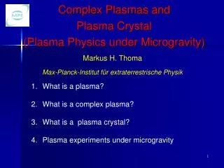
Outline • Objectives • Experimental setup and procedure • Observation of crystal growth fronts • Identification of different states • Identification of detailed growth process • Comparison with numerical simulations • Summary
Objectives for our experiments Study of dynamics of single particles during crystallisation in real time without changing the plasma parameters Questions: What are the self-organisation principles governing crystal growth? What is the resultant surface structure and its temporal evolution? What is the microscopic (kinetic) structure of interfaces?
Formation and Growth of Plasma Crystals Experimental parameters: Particle diameter: 1,28 µm ± 0,056 µm Particle number: ~ 107 Gas: Argon Gas pressure p = 0.23 mbar Laser sheet thickness: 80-250 µm Images: 1028 * 772 Pixel Intensity values: 8 bitImage rate: 15 images/sec 40*30 mm overview camera6.4*4.8 mm high resolution camera Experimental procedure: A large vertically extended crystal (~80 µm lattice distance) is created (no horizontal layers!) The system is disturbed by decreasing the ionization voltage from 0.88 V down to 0.39 V. The recrystallisation is investigated. Overview High resolutioncamera High resolution
Experimental observation – color codedmovie Particles fall down The crystal dissolves from top to bottom The crystallisation process starts at the bottom A crystallisation front is observed The propagation velocity of the crystallisation front slightly decreases Domains of different lattice orientation form below the front At the interface the thermal velocity of the particles is higher 6.4*4.8 mm, 15 Hz, superposition of 10 consecutive image
Discovery of interfacial melting 16 sec later Discovery of different crystal domains : a stable region of interfacial melting (a few lattice thicknesses) is located between two lattice domains. Similar phenomena have also been observed in colloidal systems.
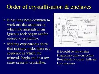
Comparison of structures- before voltage decreaseTriangulation • No horizontal crystal layers (no influence of electrodes) • Plasma crystal is oriented in an arbitrary angle towards the plane of the laser sheet • No information about 3d structure Lattice distance: 80 mm
Comparison of structures – after recrystallisationTriangulation Lattice distance: 75 mm
NumericalResults – Crystal Growth 2 D simulation box (molecular dynamics simulation, gravity, shielded Coulomb potential, neutral gas damping, Ar, Q=3000e, initial velocity is Gauss distributed with 3cm/sec, parabolic potential). Fast dropping particles disturb the upper part of the crystal. They exchange their energy through Coulomb collisions . Energy dissipation: shock-and compressional waves). Boris Klumov
Sedimentation – after power variation 40 sec later 40 sec later Particles: 1.28 mm Ueff (top)=22.7 V, Ueff (bottom)=22.8 VURF (forward)=0.39 V, URF (backward)=0.018 V Pressure: 0.25 mbar Experimental procedure: Voltage is increased (from 40 to 140 levels) and then quickly decreased back. Vertical extension and particle distance decrease with time.
Cooling - Numerical result fcc, hcp and a small amount of bcc structure is present. The final ground state (fcc) is reached much slower than predicted by neutral gas damping (fcc/hcp volume ratio increases with time). A reason might be that particles have a small size (charge) variation. This allows a large number of possible crystalline states. During the sedimentation the particles slowly rearrange to the state with lowest potential energy (very slow process – driven by thermal motion In experiment: the cooling is slower - additional heating?. Boris Klumov
Particle positions Velocities in the yellow region Mean velocity & Growth velocity Velocity distribution
ParticleVelocity Variation – NumericalResultatfixed time 3D simulation: Yukawa System crystallises from bottom upward (due to gravitational compression, box no periodic conditions). The particle’s thermal velocity increases upward and reaches a local minimum at the position of the growing crystal front. Boris Klumov
Quantitative phase separation Overlap technique: - In the crystalline state particles overlap almost completely in consecutive images, in the disturbed (liquid) state they do not. - Superposition of n images: Determination of ratio of overlapping particle area in all n images/particle area in the first image 1: particle is stationary 0: particle has moved further than its image size
The „overlap“ technique Particle 1 (Frame 1) Particle 2 (Frame 1)
The „overlap“ technique Particle 1 Frame 1+2 Ratio ~ 0.1 Particle 2 Frame 1+2 Ratio ~ 0.9 This yields a quantitative measure of particle kinetic energy
Discovery of „nanocrystallites“ and „nanodroplets“ during crystal growth crystallite droplet Rubin-Zuzic et al. (Nature Physics,2006)
Fractal dimension of crystallisation front Determination of the (linear) fractal dimension of the crystallisation front to obtain a quantitative measure for the variation of the interface front during the growth process: 1 2 Ln = n (length of „measuring rod“) L = length of crystallisation front
Fractal dimension of (1D) crystallisation front log (L) 2.200 -> surface structure is scale-free 2.100 a= - 0.2 -> D = 1.19 2.000 2 0.3 0.5 0.7 0.9 1.1 Log (n)
Fractal dimension of the crystallisation front Rough surface Smooth surface crystal growth follows a universal self-organization pattern at the particle level
MD simulations of the crystallization front Growth velocity crucial role of the dimensionality in strongly coupled systems – only the 3D simulations provide quantitative agreement with the experimental data (open circle) Particle positions and thermal energies Thermal velocities front has a complex structure with a transition layer and transient “temperature islands” Boris Klumov
Summary (crystallisation experiment) Crystallisation starts mostly from bottom, because there the compression is higher (due to gravity) than on top Crystal is build up with particles from the gaseous state located above. During crystallisation theparticles in the “liquid” state lose energy through collisions with neighbours.Energy is dissipated by waves, which are propagating through the crystal medium (see numerical results). Interfacial melting has been observed between domains, the layer is only 2-4 lattice planes wide. The (transient) energy sourcecould be the latent energy of converting an excited lattice state (hcp) into a lower (ground) state (fcc). The transition region is characterised by numerous droplets (in the crystal regime) and crystallites(in the fluid regime) and oscillating variaton in roughness. The crystallisation front obeys a universal fractal law down to the (minimum) lattice spacing. Next steps:new camera (higher temporal and spatial resolution), fast 3D scans during crystallisation, identification of 3D crystal structure variation during crystal growth, … Future:Investigation on the ISS