Download
1 / 8
80 likes | 209 Vues
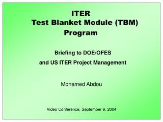
Neutronics Analysis for K-DEMO Blanket Module w ith Helium coolant. June 26, 2013 Presented by Kihak IM Prepared by Y.S. Lee Fusion Engineering Center DEMO Technology Division / In-Vessel Component Team. PPPL-NFRI Meeting, June 26-28, 2013, at PPPL.

E N D
Neutronics Analysis for K-DEMO Blanket Module with Helium coolant June 26, 2013 Presented by Kihak IM Prepared by Y.S. Lee Fusion Engineering Center DEMO Technology Division / In-Vessel Component Team PPPL-NFRI Meeting, June 26-28, 2013, at PPPL
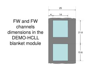
Thickness of Blanket Layers in the Current K-DEMO • Inboard Blanket [Thickness = 1,050 mm] FW Inb. Blanket 28 200 150 50 59 302 75 31 155 Manifold& Structures Be Be Shield W FW – 4 mm RAFM ~ 15 mm He Channel ~ 10 mm RAFM – 2 mm Li4SiO4 Structural Material Cooling channel W Be B4C Ceramic pebble breeder • Outboard Blanket [Thickness = 1,200 mm] Outb. Blanket FW 452 28 200 150 50 59 75 31 155 Manifold& Structures Be Be Shield
Concept of Blanket (One Module) Cooling Channel • FW requires a dedicated cooling channel…. (Peak) 3 MW/m2 neutron wall load + ~0.5 MW/m2 radiation heat load (fcore_rad = 0.5) Maximum neutron wall load area Theother8 cooling channels, 6 mm wide each, have common inlet/outlet
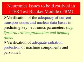
Neutronic Analysis Model for Inboard/Outboard Blanket (One Module)for Thickness Optimization between Layers 54.8 100 100 3 MW neutron (max.) = 2.13x10¹⁸ n/s [unit in cm] • Shielding behind the breeding blanket • is not included yet.
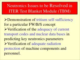
Neutronics Analysis NOT ENOUGH to meet global TBR >1, considering non-breeding zone, such as divertor and ports. Neutron Reflection B.C. at sides Neutron Back-scattering at front (~10% ?) • Accumulated TBR = 1.134 • (for one module) (Minor) Neutron penetration at back side 54.8 100 100 • If neutron back-scattering at front is counted in, • TBR could be increased by ~10% (?). • 3D full sector model is required to get reliable TBR • 3D sector model is under construction… [unit in cm]
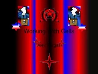
Generated Heat in the individual layer (for NWL = 3 MW) Be Li Breeder Some heat generation in W and RAFM Important data for cooling design • 3.3 MW (Energy multiplication factor = 1.1) • Could be increased if back-scattered neutrons are counted in
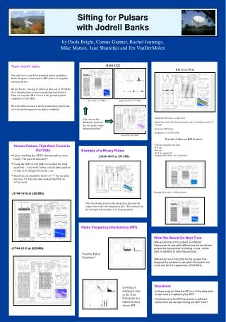
Power density in the HCCB module Li-breeder (exo-thermic reaction) Tungsten • Power density is higher in tungsten and Li-breeding zones
FutureWork • Model expansion is on-going to cover 3-D, 22.5 degree toroidal sector of both inboard and outboard blankets, to consider the reflected neutrons and global TBRs. • will give more reliable global TBR… • Shieldingwillbeadded and optimized. 54.8 100 100 • T-H analyses are on-going in parallel at the moment for appropriate cooling design.