DC Circuits: Review
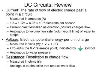
DC Circuits: Review. Current : The rate of flow of electric charge past a point in a circuit Measured in amperes (A) 1 A = 1 C/s = 6.25 10 18 electrons per second Current direction taken as direction positive charges flow

DC Circuits: Review
E N D
Presentation Transcript
DC Circuits: Review • Current: The rate of flow of electric charge past a point in a circuit • Measured in amperes (A) • 1 A = 1 C/s = 6.25 1018 electrons per second • Current direction taken as direction positive charges flow • Analogous to volume flow rate (volume/unit time) of water in a pipe • Voltage: Electrical potential energy per unit charge • Measured in volts (V): 1 V = 1 J/C • Ground is the 0 V reference point, indicated by symbol • Analogous to water pressure • Resistance: Restriction to charge flow • Measured in ohms (W) • Analogous to obstacles that restrict water flow
A Helpful Hydraulic Analogy College Physics, Giambattista
(Lab 1–1) A Simple DC Circuit • Resistors have a constant resistance over a broad range of voltages and currents • Then with R = constant (Ohm’s law) • Power = rate energy is delivered to the resistor = rate energy is dissipated by the resistor V V
(Lab 1–4, 1–6) Voltage Divider • Voltage divider: Circuit that produces a predictable fraction of the input voltage as the output voltage • Schematic: • Current (same everywhere) is: • Output voltage (Vout) is then given by: R1 (Student Manual for The Art of Electronics, Hayes and Horowitz, 2nd Ed.) R2
R1 R2 Voltage Divider • Easier way to calculate Vout: Notice the voltage drops are proportional to the resistances • For example, if R1 = R2then Vout = Vin / 2 • Another example: If R1 = 4 W and R2 = 6 W, then Vout = (0.6)Vin • Now attach a “load” resistor RLacross the output: • You can model R2 and RL as one resistor (parallel combination), then calculate Vout for this new voltage divider R1 R1 = R2 RL R2 RL
R1 R2 R1 Vin Vout R2 Voltage Dividers on the Breadboard R1 R2 R1 R2
Interactive Example:Fun With a Loaded Function Generator Interactive activity performed in class.
Ideal Voltage and Current Sources • An ideal voltage source is a source of voltage with zero internal resistance (a perfect battery) • Supply the same voltage regardless of the amount of current drawn from it • An ideal current source supplies a constant current regardless of what load it is connected to • Has infinite internal resistance • Transistors can be represented by ideal current sources (Introductory Electronics, Simpson, 2nd Ed.)
Ideal Voltage and Current Sources • Load resistance RL connected to terminals of a real current source: • Larger current is through the smaller resistance • Current sources can always be converted to voltage sources • Terminals A’B’ act electrically exactly like terminals AB (Introductory Electronics, Simpson, 2nd Ed.) (Introductory Electronics, Simpson, 2nd Ed.)
Thevenin’s Theorem • Thevenin’s Theorem: Any combination of voltage sources and resistors with 2 terminals is electrically equivalent to an ideal voltage source in series with a single resistor • Terminals A’B’ electrically equivalent to terminals AB • Thevenin equivalent VTh and RTh given by: RTh (Introductory Electronics, Simpson, 2nd Ed.) VTh (output voltage with no load attached) I (short circuit) = current when the output is shorted directly to ground
(Lab 1–4) Thevenin’s Theorem • Thevenin’s theorem applied to a voltage divider: • Thevenin equivalent circuit: • Note that RTh = R1 R2 • Imagine mentally shorting out the voltage source • Then R1 is in parallel with R2 • RTh is called the output impedance(Zout) of the voltage divider R1 R2 RTh (a load resistance RL can then be attached between terminals A’ and B’, in series with RTh) (Introductory Electronics, Simpson, 2nd Ed.) VTh
Example Problem #1.9 (The Art of Electronics, Horowitz and Hill, 2nd Ed.) Solution (details given in class): • 15 V • 10 V • VTh = 15 V, RTh = 5k • 10 V • PL = 0.01 W, PR2 = 0.01 W, PR1 = 0.04 W For the circuit shown, with Vin = 30 V and R1 = R2 = 10k, find (a) the output voltage with no load attached (the open-circuit voltage); (b) the output voltage with a 10k load; (c) the Thevenin equivalent circuit; (d) the same as in part b, but using the Thevenin equivalent circuit (the answer should agree with the result in part b); (e) the power dissipated in each of the resistors.
(see AE 1) Norton’s Theorem • Norton’s Theorem: Any combination of voltage sources and resistors with 2 terminals is electrically equivalent to an ideal current source in parallel with a single resistor • Terminals A’B’ electrically equivalent to terminals AB • Norton equivalent IN and RN given by: IN RN (Introductory Electronics, Simpson, 2nd Ed.) (same as Thevenin equivalent resistance) (same as I (short circuit))
Norton’s Theorem • Norton’s theorem applied to a voltage divider: • Norton equivalent circuit: • The Norton equivalent circuit is just as good as the Thevenin equivalent circuit, and vice versa R1 R2 (a load resistance RL can then be attached between terminals A’ and B’, in parallel with RN) (Introductory Electronics, Simpson, 2nd Ed.) RN IN
Example Problem #1.7 (similar to HW Problem #1.8) Ammeter What will a 20,000 W/V meter read, on its 1 V scale, when attached to a 1 V source with an internal resistance of 10k? What will it read when attached to a 10k–10k voltage divider driven by a “stiff” (zero source resistance) 1 V source? Solution (details given in class): 1–V source: 0.667 V 10k–10k voltage divider: 0.4 V Voltmeter