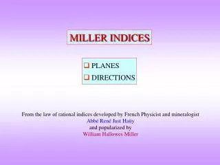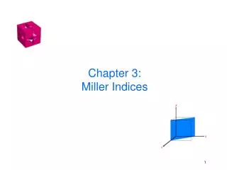
Miller Indices
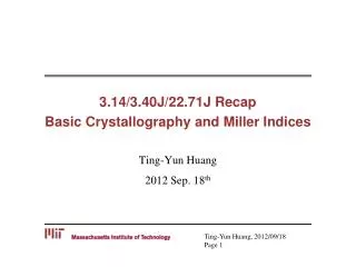
Z. Y. X. (100). Lec . ( 4,5). Miller Indices. Crystal Systems. Unit cell: smallest repetitive volume that contains the complete lattice pattern of a crystal. 7 crystal systems 14 crystal lattices. a, b and c are the lattice constants. Unit Cells Types.

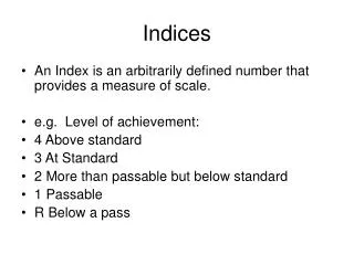
Miller Indices
E N D
Presentation Transcript
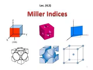
Z Y X (100) Lec. (4,5) Miller Indices
Crystal Systems Unit cell: smallest repetitive volume that contains the complete lattice pattern of a crystal. 7 crystal systems 14 crystal lattices a, b and c are the lattice constants
Unit Cells Types A unit cellis the smallest component of the crystal that reproduces the whole crystal when stacked together. • Primitive (P) unit cells contain only a single lattice point. • Internal (I) unit cell contains an atom in the body center. • Face (F) unit cell contains atoms in theall faces of the planescomposing the cell. • Centered (C) unit cell contains atomscentered on the sides of the unit cell. Face-Centered Primitive Body-Centered End-Centered Combining7 Crystal Classes(cubic, tetragonal, orthorhombic, hexagonal, monoclinic, triclinic, trigonal) with 4 unit cell types (P, I, F, C) symmetryallows for only 14 types of 3-D lattice.
(c) 2003 Brooks/Cole Publishing / Thomson Learning™ Lattice parameters in cubic, orthorhombic and hexagonal crystal systems.
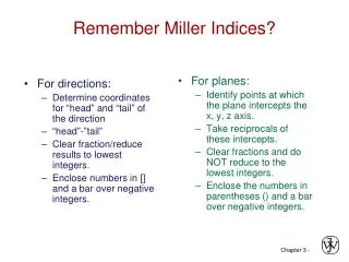
Basic definitions – Lattice sites • Define basic terms and give examples of each: • Points (atomic positions) • Vectors (defines a particular direction - plane normal) • Miller Indices (defines a particular plane) • relation to diffraction • 3-index for cubic and 4-index notation for HCP
Points, Directions and Planes in the Unit Cell • Miller indices - A shorthand notation to describe certain crystallographic directions and planes in a material. Denoted by [ ], <>, ( ) brackets. A negative number is represented by a bar over the number.
Point Coordinates • Coordinates of selected points in the unit cell. • The number refers to the distance from the origin in terms of lattice parameters.
z 111 c y 000 b a x Point Coordinates Point coordinates for unit cell center are a/2, b/2, c/2 ½½½ Point coordinates for unit cell corner are 111 Translation: integer multiple of lattice constants identical position in another unit cell z 2c y b b
[111] where overbar represents a negative index => Crystallographic Directions Algorithm [111] z 1. Vector repositioned (if necessary) to pass through origin.2. Read off projections in terms of unit cell dimensions a, b, and c3. Adjust to smallest integer values4. Enclose in square brackets, no commas [uvw] [201] y x ex:1, 0, ½ => 2, 0, 1 => [201] -1, 1, 1
c b a • 5. Designate negative numbers by a bar • Pronounced “bar 1”, “bar 1”, “zero” direction. 6. “Family” of [110] directions is designated as <110>. DIRECTIONS will help define PLANES (Miller Indices or plane normal). Directions in a Crystal • Procedure: • Any line (or vector direction) is specified by 2 points. • The first point is, typically, at the origin (000). • Determine length of vector projection in each of 3 axes in units (or fractions) of a, b, and c. • X (a), Y(b), Z(c) • 1 1 0 • Multiply or divide by a common factor to reduce the lengths to the smallest integer values, u v w. • Enclose in square brackets: [u v w]: [110] direction.
210 Examples X = 1 , Y = ½ , Z = 0 [1 ½ 0] [2 1 0] X = ½ , Y = ½ , Z = 1 [½ ½ 1] [1 1 2]
When we write the direction [n1n2n3] depending on the origin, negative directions are written as R = n1a1 + n2a2 + n3a3 To specify the direction, the smallest possible integers must be used. Z direction - X direction (origin) O - Ydirection X direction - Z direction Negative Directions Y direction 12
Examples of Crystal Directions X = 1 , Y = 0 , Z = 0 [1 0 0] X = -1 , Y = -1 , Z = 0 [110] 13
Examples A vector can be moved to the origin. X =-1 , Y = 1 , Z = -1/6 [-1 1 -1/6] [6 6 1] 14
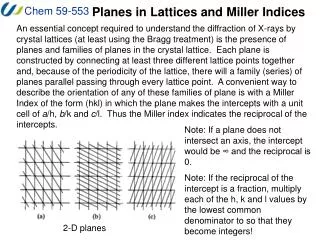
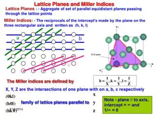
Within a crystal lattice it is possible to identify sets of equally spaced parallel planes. These are called lattice planes. In the figure, the density of lattice points on each plane of a set is the same & all lattice points are contained on each set of planes. b b a a Crystal Planes The set of planes for a 2D lattice. 15
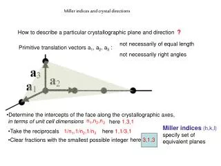
Crystallographic Planes • If the plane passes through origin, either: • Construct another plane, or • Create a new origin • Then, for each axis, decide whether plane intersects or parallels the axis. • Algorithm for Miller indices 1. Read off intercepts of plane with axes in terms of a, b, c 2. Take reciprocals of intercepts 3. Reduce to smallest integer values 4. Enclose in parentheses, no commas.
Crystallographic Planes • Crystallographic planes are specified by 3 Miller Indices (h k l). All parallel planes have same Miller indices.
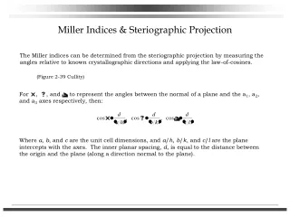
Miller Indices are a symbolic vector representation for the orientation of an atomic plane in a crystal lattice & are defined as the reciprocals of the fractional intercepts which the plane makes with the crystallographic axes. To find the Miller indices of a plane, take the following steps: Determine the intercepts of the plane along each of the three crystallographic directions. Take the reciprocals of the intercepts. If fractions result, multiply each by the denominator of the smallest fraction. Miller Indices 18
example example abc abc z 1 1 1. Intercepts c 1/1 1/1 1/ 2. Reciprocals 1 1 0 3. Reduction 1 1 0 y b a z x 1/2 1. Intercepts c 1/½ 1/ 1/ 2. Reciprocals 2 0 0 3. Reduction 2 0 0 y b a x Crystallographic Planes 4. Miller Indices (110) 4. Miller Indices (200)
z c 1/2 1 3/4 1. Intercepts 1/½ 1/1 1/¾ 2. Reciprocals 2 1 4/3 y b a 3. Reduction 6 3 4 x Crystallographic Planes example a b c 4. Miller Indices (634)
(012) Determine the Miller indices for the plane shown in the sketch xyz Intercepts Intercept in terms of lattice parameters Reciprocals Reductions Enclosure a -b c/2 -1 1/2 0 -1 2 N/A
Ex: {100} = (100), (010), (001), (100), (001) (010), Family of Planes • Planes that are crystallographically equivalent have the same atomic packing. • Also, in cubic systems only, planes having the same indices, regardless of order and sign, are equivalent. • Ex: {111} = (111), (111), (111), (111), (111), (111), (111), (111) _ _ _ _ _ _ _ _ _ _ _ _
(1,0,0) Example-1
(0,1,0) (1,0,0) Example-2
(0,0,1) (0,1,0) (1,0,0) Example-3
(0,1,0) (1/2, 0, 0) Example-4
Miller Indices Plane intercepts axes at [2,3,3] 2 Z Z Z Reciprocal numbers are: 2 3 Y Y Y X X X (100) (110) (111) Indices of the plane (Miller): (2,3,3) Indices of the direction: [2,3,3] (200) (100)
Example 7 31
SUMMARY • Crystallographic points, directions and planes are specified in terms of indexing schemes. • Materials can be single crystals or polycrystalline. • Material properties generally vary with single crystal orientation (anisotropic), but are generally non-directional (isotropic) in polycrystals with randomly oriented grains. • Some materials can have more than one crystal structure. This is referred to as polymorphism (or allotropy).
Reciprocal Lattice • A crystal resides in real space. The diffraction pattern of the crystal in Fraunhofer diffraction geometry resides in Reciprocal Space. In a diffraction experiment (powder diffraction using X-rays, selected area diffraction in a TEM), a part of this reciprocal space is usually sampled. • From the real lattice the reciprocal lattice can be geometrically constructed. The properties of the reciprocal lattice are ‘inverse’ of the real lattice → planes ‘far away’ in the real crystal are closer to the origin in the reciprocal lattice. • As a real crystal can be thought of as decoration of a lattice with motif; a reciprocal crystal can be visualized as a Reciprocal Lattice decorated with a motif* of Intensities.Reciprocal Crystal = Reciprocal Lattice + Intensities as Motif* • The reciprocal of the ‘reciprocal lattice’ is nothing but the real lattice! • Planes in real lattice become points in reciprocal lattice and vice-versa.
Motivation for constructing reciprocal lattices • In diffraction patterns (Fraunhofer geometry) (e.g. SAD), planes are mapped as spots (ideally points). Hence, we would like to have a construction which maps planes in a real crystal as points. • Apart from the use in ‘diffraction studies’ we will see that it makes sense to use reciprocal lattice when we are dealing with planes. • As the index of the plane increases → the interplanar spacing decreases → and ‘planes start to crowd’ around the origin in the real lattice (refer figure). Hence, we work in reciprocal lattice when dealing with planes. As seen in the figure the diagonal is divided into (h + k) parts.
Let us start with a one dimensional lattice and construct the reciprocal lattice Real Lattice Reciprocal Lattice How is this reciprocal lattice constructed One unit cell • The plane (2) has intercept at ½, plane (3) has intercept at 1/3 etc. • As the index of the plane increases it gets closer to the origin (there is a crowding towards the origin) Real Lattice Note in 1D planes are points and have Miller indices of single digit (they have been extended into the second dimension (as lines) for better visibility Each one of these points correspond to a set of ‘planes’ in real space Reciprocal Lattice Note that in reciprocal space index has NO brackets
Reciprocal Lattice Now let us construct some 2D reciprocal lattices Each one of these points correspond to a set of ‘planes’ in real space Example-1 Real Lattice Reciprocal Lattice g vectors connect origin to reciprocal lattice points The reciprocal lattice has an origin! Overlay of real and reciprocal lattices Note that vectors in reciprocal space are perpendicular to planes in real space (as constructed!) But do not measure distances from the figure!