Download
1 / 18
220 likes | 519 Vues
Planes in Lattices and Miller Indices.

E N D
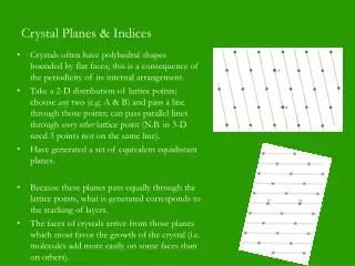
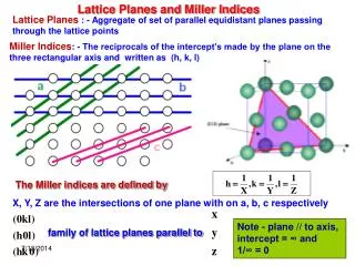
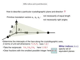
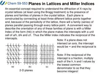
Planes in Lattices and Miller Indices An essential concept required to understand the diffraction of X-rays by crystal lattices (at least using the Bragg treatment) is the presence of planes and families of planes in the crystal lattice. Each plane is constructed by connecting at least three different lattice points together and, because of the periodicity of the lattice, there will a family (series) of planes parallel passing through every lattice point. A convenient way to describe the orientation of any of these families of plane is with a Miller Index of the form (hkl) in which the plane makes the intercepts with a unit cell of a/h, b/k and c/l. Thus the Miller index indicates the reciprocal of the intercepts. Note: If a plane does not intersect an axis, the intercept would be ∞ and the reciprocal is 0. Note: If the reciprocal of the intercept is a fraction, multiply each of the h, k and l values by the lowest common denominator to so that they become integers! 2-D planes
Planes in Lattices and Miller Indices b a (110) planes (130) planes (-210) planes
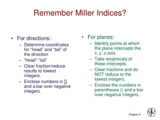
Planes in Lattices and Miller Indices The orientation of planes is best represented by a vector normal to the plane. The direction of a set of planes is indicated by a vector denoted by square brackets containing the Miller indices of the set of planes. Miller indices are also used to describe crystal faces. (100) planes [100] vector (-100) face (100) face
Planes in Lattices and Miller Indices A summary of notation that you will see in regard to planes and/or crystal faces: (hkl) denotes a set of planes [hkl] designates a vector (the direction of the planes) {hkl} set of faces made equivalent by the symmetry of the system, thus: {100} for point group 1 this refers only to the (100) face {100} for point group -1 this refers to (100) and (-100) faces for mmm {111} implies (111),(11-1),(1-11),(11-1),(-1-11),(-11-1),(1-1-1),(-1-1-1)
Planes in Lattices and Miller Indices Pictures from: http://www.gly.uga.edu/schroeder/geol6550/millerindices.html
Planes in Lattices and Miller Indices Note that for hexagonal systems, the Miller-Bravais indices are often used instead. These have the form (hkil), where h, k, and i are the reciprocals of the plane intercepts for the three co-planar vectors indicated below and l is the reciprocal for the intercept in the c direction. Note that h, k and i are not linearly independent so the rule h+k+i = 0 must always be obeyed. a b
Planes in Lattices and Bragg’s Law We are interested in the planes in a crystal lattice in the context of X-ray diffraction because of Bragg’s Law: nl = 2 d sin(q) Where: n is an integer l is the wavelength of the X-rays d is distance between adjacent planes in the lattice q is the incident angle of the X-ray beam Bragg’s law tells us the conditions that must be met for the reflected X-ray waves to be in phase with each other (constructive interference). If these conditions are not met, destructive interference reduces the reflected intensity to zero! W.H.Bragg and son W.L.Bragg were awarded the Nobel prize in 1915.
Simple derivation of Bragg’s Law Bragg’s Law can be derived using simple geometry by considering the distances traveled by two parallel X-rays reflecting from adjacent planes. The X-ray hitting the lower plane must travel the extra distance AB and BC. To remain in phase with the first X-ray, this distance must be a multiple of the wavelength thus: nl = AB+BC = 2AB (since the two triangles are identical) The distance AB can be expressed in terms of the interplanar spacing (d) and incident angle (q) because d is the hypotenuse of right triangle zAB shown at right. Remember sin = opposite/hypotenuse sin(q) = AB/d thus AB = d sin(q) Therefore: nl = 2 d sin(q) Note: d and sin(q) are inversely proportional (reciprocal). This means that smaller values of d diffract at higher angles – this is the importance of “high angle” data!
Diffraction of X-rays You may wonder why to X-rays reflect in this way and what is causing them to “reflect” in the first place. The actual interaction is between the X-rays and the ELECTRONS in the crystal and it is a type of elastic scattering. The oscillating electric field of the X-rays causes the charged particles in the atom to oscillate at the same frequency. Emission of a photon at that frequency (elastic) returns the particles in the atom to a more stable state. The emitted photon can be in any direction and the intensity of the scattering is given by the equation: I(2q) = Io [(n e4)/(2 r2 m2 c4)] [(1 + cos2(2q))/2] I(2q) = observed intensity Io = incident intensity n = number of scattering sources r = distance of detector from scattering source m = mass of scattering source c = speed of light, e = electron charge, [(1 + cos2(2q))/2] is a polarization factor Note that the mass of the scattering particle (m) is in the denominator – this means that the scattering that we see is attributable only to the electrons (which have masses almost 2000 times less than that of a proton).
Laue’s interpretation Max von Laue derived a different set of equations describing the “in phase” diffraction of X-rays by a line of scattering objects (note that the n in the diagram below is the integer corresponding to the integer n in the Bragg equation). Each line of objects generates cones of “in phase” scattering that follow the equations: a(cos Y1 – cos j1) = lh (for a line in the a direction) b(cos Y2 – cos j2) = lk (for a line in the b direction) c(cos Y3 – cos j3) = ll (for a line in the c direction) Where Y is the angle between the incident beam and the line and j is the angle between the cone and the line of scatterers. In three dimensions, a reflection will only be observed at the intersection of the cones in all three directions (all three equations are satisfied). With a little geometry (see Ladd and Palmer 3.4.3), it can be shown that this treatment is equivalent to Bragg’s law.
Summary of Diffraction by Planes If they interact with electrons in the crystal, incident X-rays will be scattered. Only the X-rays that scatter “in phase” (constructive interference) will give rise to reflections we can observe. We can use Bragg’s Law to interpret the diffraction in terms of the distance between lattice planes in the crystal based on the incident and diffraction angle of the reflection. Note: The diffraction angle is generally labeled 2q because of the geometric relationship shown on the left.
The Reciprocal Lattice Because of the reciprocal nature of d spacings and q from Bragg’s Law, the pattern of the diffraction we observe can be related to the crystal lattice by a mathematical construct called the reciprocal lattice. In other words, the pattern of X-ray reflections makes a lattice that we can use to gain information about the crystal lattice. The reciprocal lattice is constructed as follows: Choose a point to be the origin in the crystal lattice. Let the vector normal to a set of lattice planes in the real lattice radiate from that origin point such that the distance of the vector is the reciprocal of the d spacing for each family of planes. i.e. the vector for the plane (hkl) has a distance of 1/d(hkl) (or, more generally K/d(hkl)). Repeat for all real lattice planes. You can see how this works at: http://www.doitpoms.ac.uk/tlplib/reciprocal_lattice/index.php or: http://www.xtal.iqfr.csic.es/Cristalografia/index-en.html
The Reciprocal Lattice This procedure constructs a reciprocal lattice (RL) in which each lattice point corresponds to the reflection that is generated by a particular family of planes. This lattice can easily be indexed by assigning the proper (hkl) value to each lattice point. • Note that consequence of this reciprocal relationship include: • Large d spacings correspond to small spacings in the RL – this is an important feature that must be considered during data collection. • - Obtuse angles in the real lattice correspond to obtuse angles in the RL
The Reciprocal Lattice For those of you who are comfortable with vectors, here is how the reciprocal lattice is built: Note that : a· a* = 1 (etc. – this is the reciprocal part) a · b* = 0 (etc. – the vectors are orthogonal in this geometry) Thus the reciprocal lattice can be represented by vectors of the form: Rhkl = ha* + kb* + lc*,| Rhkl | = K / dhkl where h, k, and l are the indices of sets of planes in the crystal, and K can assume the value of 1, λ, or 2πλ, depending on the user's convention (crystallography, solid-state physics, etc). In later discussions, K will be assumed to have a value of 1. K is shown in the relations below for completeness. Thus the individual lattice vectors have the following definitions: a* = K (b × c) / (a · (b × c)) a = (b* × c*) / K (a* · (b* × c*)) b* = K (c × a) / (b · (c × a)) b = (c* × a*) / K (b* · (c* × a*)) c* = K (a × b) / (c · (a × b)) c = (a* × b*) / K (c* · (a* × b*)) cosα* = (cosβ cosγ - cosα) /( sinβ sinγ) cosα = (cosβ* cosγ* - cosα*) /( sinβ* sinγ*) cosβ* = (cosα cosγ - cosβ) /( sinα sinγ) cosβ = (cosα* cosγ* - cosβ*) /( sinα* sinγ*) cosγ* = (cosα cosβ - cosγ) /( sinα sinβ) cosγ = (cosα* cosβ* - cosγ*) /( sinα* sinβ*) V = a · b × c = 1/V* = abc √ (1 - cos2α - cos2β - cos2γ + 2 cosα cosβ cosγ) V* = a* · b* × c* = 1/V = a*b*c* √ (1 - cos2α* - cos2β* - cos2γ* + 2 cosα* cosβ* cosγ*)
The Reciprocal Lattice Some of the important relationships between the real lattice and the reciprocal lattice (in non-vector notation) are summarized here. Note that K = 1 in these equations.