Download
1 / 32
320 likes | 424 Vues
Explore automated pen & ink illustration with B-Spline models, emphasizing NPR approach and minimizing noise. Learn about Bezier and B-Spline surfaces for enhancing rendering quality.

E N D
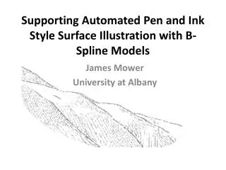
Supporting Automated Pen and Ink Style Surface Illustration with B-Spline Models James Mower University at Albany
Perspective Landscape Rendering • Demonstrated in Tuscan landscape paintings by da Vinci • Extended towoodcuts inthe 16thcentury byMurer andothers
Automating Pen and Ink Illustration • Apply a non-photorealistic rendering (NPR) approach • Use an “economy of lines” • Markosian and others, 1997 • Depict the essential form of an object using a minimal number of strokes
Linework • Landscape featuresare representedwith 2 types oflinework • Silhouettes • Boundaries betweenvisible and invisiblesurfaces • Form Lines • Surface trends W.M. Davis
Representing Elevation • More samples, less interpolation • TIN • Polyhedron • Interpolated values lie on plane • Fewer samples, more interpolation • “Global” polynomial functions of order p • Polynomial patches of order p • Interpolated values evaluate to degree p-1 surface
But Which Is Best? • Manual pen and ink style landscape illustrations usually depict low noise surfaces • Dense sampling models have lots of noise • Some NPR techniques are sensitive to noise • Can generate numerous junk silhouettes • Bezier surface models supress noise and are good candidates for NPR support
Bezier Surface Models • A Bezier surface is described by control points • Its order in u and v equals the number of control points along the respective axes • Each control point is associated with a basis function • The basis function determines the control point’s influence on the surface at position u,v
A Bezier Surface A degree 3 by degree 3 Bezier Surface Generated from a Java applet created by David Little, Department of Mathematics, Penn State
A Problem with Bezier Surfaces • Evaluation times increase exponentially with the number of control points • Computations on large numbers of control points can lead to numerical overflow • Solution—B-Spline surfaces • A patchwork of low order Bezier surfaces • Stitched together at their edges with continuous joins
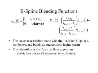
B-Spline Surface Model • Composed of local ‘basis’ functions that only contribute within a given ‘knot span’ • The continuity at the joins is determined by: • The degree of the basis functions in u and v • The number of duplicate knot values at the join • This project uses degree 3 basis functions with 2 times differentiability at the joins
A B-Spline Surface 10 degree 3 by degree 3 patches are stitched together with 2 times differentiability at patch borders
Surface Tessellation • Polynomial surfaces are rendered as a set of planar facets (a tessellation) • The facets should cover aboutthe same screen space, regardless of their position in the world • The OpenGL B-spline rendering functions enforce this criterion
Gray Shaded B-Spline Surface Rendering this surface in emissive white makes it a useful surface mask for silhouette and form line rendering
Surface Processing Environment • OpenGL • NURBS package • CGAL • Computational Geometry and Algorithms Library • Fast triangulation • Useful geometric modeling operations and primitives • Written in C++ for MS Windows
Defining Form Lines • A form line shows a surface trend • Form lines can be defined globally or locally • This project defines a form line segment as a line of steepest descent from one vertex to an adjacent neighbor • Form lines are visual composites of locally generated segments
The Form Line Model The weighted illumination and slope components control shading for a surface facet
Rendering Parameters • Illumination azimuth and altitude • Position and attitude of the viewpoint • Line width • Silhouette line widths are constant over the image • Form line width varies with slope and lighting • Weighting of slope and illumination • Both vary between 0 and 1 such that iw = 1 – sw
Varying Illumination Azimuth West Temple feature, Zion National Park 72 images, illumination azimuth rotating through 360 degrees at 5 degrees per image
Level of Detail Varies with the Viewpoint Position 100 still images on an 8 km flight path
Critique • What types of landscapes work best with this rendering model? • Rugged terrain with rock faces • Good form line control through slope and llumination weighting • What types don’t work well? • Smooth, rolling hills • Overrepresentation of form lines
Using Fewer Form Lines • This W.M. Davis image uses very few strokes • It could be simulatedwith knowledge ofregional structures • A drainage basin could serve as a region for localsurface modeling
Using Drainage Accumulation Models • Drainage segments could be classified by flow values or stream order • Form lines couldbe composed of drainage segments withinselected ranges Simulated Effect
Performance Statistics • For 214,407 triangles tessellated from the surface for the sample images, • CGAL Delaunay triangulation: 178 seconds • OpenGL B-spline rendering: 407 seconds • Form line rendering: 2 seconds • Clearly, most of the time is spent performing B-spline tessellation and rendering • OpenGL NURBS interface is written entirely in software
Performance Improvements • Implement Cox-DeBoor surface model • Do polygon shading on GPU with shader routine • Do my own tessellation • Use cheapest possible triangulation, assuming that tessellation will produce relatively uniform distribution of vertices
Future Work • Implement faster surface evaluation and tessellation • Work on ‘ultra minimal’ representations • Fine tune parameters for surface types
Thanks for Coming! • The paper can be found at http://www.albany.edu/faculty/jmower/geog/publications/ • Any questions?