Download
1 / 49
510 likes | 1.11k Vues
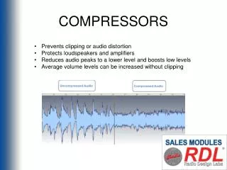
Learn about the anatomy, operation, and control of various types of fans, blowers, and compressors. Understand the principles of fluid dynamics, thermodynamics, and performance data analysis in these machines.

E N D
Fans, Blowers and Compressors P M V Subbarao Professor Mechanical Engineering Department I I T Delhi Machines to Generate Lively Gases….
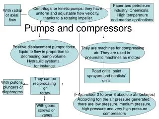
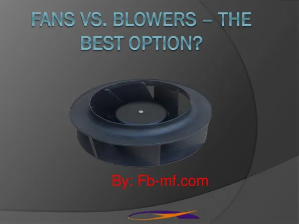
Centrifugal Fan Operation Fans cause a pressure increase through two methods Centrifugal force is created by the rotation of the column of air trapped between two blades. Kinetic energy is supplied to the air through the impeller Total pressure = static pressure + velocity head Blades are backward-curved, forward curved, or radial (straight) Airfoil-types are complex and expensive but very efficient; they’re used for large systems where the cost is justified.
Axial Flow Fans • Common types: propeller, tubeaxial, vaneaxial • Tubeaxial: impeller is inside a tube to guide airflow and improve performance. • Vane axial: like a tube axial except vanes downstream of the impeller are used to reduce swirl and improve performance • Used to deliver large flow rates but small increase in pressure • Examples include fans used for ventilation without ductwork, mobile room fans, and fans used to cool computers. • Tube-axial fan for computer cooling • Tube-axial fan for ventilation • Vane-axial fan for high air resistance electronics cooling • Straightening vanes are located inside tube.
Fan Laws Operational and performance data of different but geometrically similar fans can be cast onto a single universal curve using dimensionless numbers
Fan Flow Control • Fans rarely are operated continuously at the same pressure and volume discharge rates. • There exists a need for a system which can vary the vane output according to requirements. • Common methods of controlling fan output are: • Damper control • Inlet vane control • Variable speed control. • Axial fans can control flow using variable pitch blades.
Characteristic Curves: Radial Vane Centrifugal Fan Static Pressure Efficiency Power
Characteristic Curves: Forward Vane Centrifugal Fan Noise Level Static Pressure Power Efficiency
Characteristic Curves: Backward Vane Centrifugal Fan Noise Level Power Static Pressure Efficiency
Comparison of Fan Characteristic Curves : Static Pressure Static Pressure Backward Forward
Characteristic Curves: Axial Fan Noise Level Power Static Pressure Efficiency
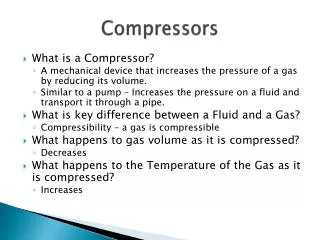
Classification of Compressors Rotodynamic Compressors Positive Displacement of Compressors Centrifugal Compressors Mixed Compressors Axial Compressors Reciprocating Compressors Rotory Compressors
Duty of Compressors • A two step life infusion into gas. • Rotor : Mostly Energy Transfer • The centrifugal compressor consists essentially of a stationary casing containing a rotating impeller which imparts a high velocity to the air. • Only Energy Conversion: • A number of diverging passages (Diffuser) in which the air is decelerated with a consequent rise in static pressure.
Centrifugal Compressors • Air is sucked into the impeller eye and whirled round at high speed by the vanes on the impeller disc. • Centripetal acceleration leads to increase in rise of some amount of static pressure. • The remaining increase in rise of pressure occurs in diffuser.
Performance of centrifugal compressors Total Pressure Ratio Design clue for Blades: The overall or total-to-total efficiency
Vane Geometry : Compressor Characteristics Pressure Ratio Mass Flow
Performance of Backward Vane Compressor b2 =90 b2 =75 b2 =60
Remarks on Centrifugal Compressors • High pressure ratio per stage (r0p= 3 to 4). • Less flow area per unit mass flow rate. • A multistage centrifugal compressors have shorter lengths. • They are best suited for low mass flow rates. • As the flow is turned by 900, the efficiency of centrifugal compressor is relatively low. • The impeller is an integral unit of blades and a disk. • Even if one blade is damaged the entire unit is to be replaced. • Look for other fluid dynamic phenomenon for ingestion of life into fluids. • Aerofoil Theory.
Evolution of Compression Phenomenon Aerofoil Centrifugal Compact & Less Efficient Bulky & More Efficient
AXIAL FLOW COMPRESSORS An Efficient Way to Ingest Life in Gases !!!
Axial Flow Fluid Machines The power, P of a fluid Machine
Similarity Analysis • Experimental performance curves or maps provide a versatile data for compressor engineers. • The data is translated into most general form. • Data in general form is minimally effected by air speed, altitude etc. • The total pressure ratio of a compressor is: Using dimensional analysis & Buckingham Pi Theorem:
Zero Efficiency Points Compressor Characteristics Maximum Efficiency point Supply pipe Compressor exit
Axial Flow Compressors: Current Design Practice Fan or low pressure Compressor
Axial Flow Compressors: Current Design Practice High pressure Compressor
GE9X : The worlds Next Great Jet Engine : 2020 6-stage turbine 14-stage compressor contributing to an overall engine pressure ratio of 60:1.