Download

1 / 31
320 likes | 410 Vues
Understand how voltage and current are distributed in series and parallel resistor configurations, with practical examples and calculations. Learn principles from Fundamentals of Electric Circuits.

E N D
Objective of Lecture • Explain mathematically how a voltage that is applied to resistors in series is distributed among the resistors. • Chapter 2.5 in Fundamentals of Electric Circuits • Chapter 5.7 Electric Circuit Fundamentals • Explain mathematically how a current that enters the a node shared by resistors in parallel is distributed among the resistors. • Chapter 2.6 in Fundamentals of Electric Circuits • Chapter 6.7 in Electric Circuit Fundamentals • Work through examples include a series-parallel resistor network (Example 4). • Chapter 7.2 in Fundamentals of Electric Circuits
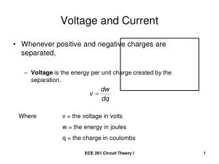
Voltage Dividers Resistors in series share the same current Vin
Voltage Dividers Resistors in series share the same current From Kirchoff’s Voltage Law and Ohm’s Law : + V1 - + V2 _ Vin
Voltage Dividers Resistors in series share the same current From Kirchoff’s Voltage Law and Ohm’s Law : + V1 - + V2 _ Vin
Voltage Division The voltage associated with one resistor Rn in a chain of multiple resistors in series is: or where Vtotal is the total of the voltages applied across the resistors.
Voltage Division • The percentage of the total voltage associated with a particular resistor is equal to the percentage that that resistor contributed to the equivalent resistance, Req. • The largest value resistor has the largest voltage.
Find the V1, the voltage across R1, and V2, the voltage across R2. Example 1 + V1 - + V2 _
Voltage across R1 is: Voltage across R2 is: Check: V1 + V2 should equal Vtotal Example 1 + V1 - + V2 _ 8.57 sin(377t)V + 11.4 sin(377t) = 20 sin(377t) V
Example 2 + V1 - + V2 - + V3 - • Find the voltages listed in the circuit to the right.
Example 2 (con’t) + V1 - + V2 - + V3 - Check: V1 + V2 + V3 = 1V
Symbol for Parallel Resistors To make writing equations simpler, we use a symbol to indicate that a certain set of resistors are in parallel. Here, we would write R1║R2║R3 to show that R1 is in parallel with R2 and R3. This also means that we should use the equation for equivalent resistance if this symbol is included in a mathematical equation.
Current Division All resistors in parallel share the same voltage + Vin _
Current Division All resistors in parallel share the same voltage From Kirchoff’s Current Law and Ohm’s Law : + Vin _
Current Division All resistors in parallel share the same voltage + Vin _
Current Division Alternatively, you can reduce the number of resistors in parallel from 3 to 2 using an equivalent resistor. If you want to solve for current I1, then find an equivalent resistor for R2 in parallel with R3. + Vin _
Current Division + Vin _
Current Division The current associated with one resistor R1in parallel with one other resistor is: • The current associated with one resistor Rmin parallel with two or more resistors is: where Itotalis the total of the currents entering the node shared by the resistors in parallel.
Current Division • The largest value resistor has the smallest amount of current flowing through it.
Example 3 Find currents I1, I2, and I3 in the circuit to the right.
Example 3 (con’t) Check: I1 + I2 + I3 = Iin
Example 4 I1 • The circuit to the right has a series and parallel combination of resistors plus two voltage sources. • Find V1 and Vp • Find I1, I2, and I3 + V1 _ I2 I3 + Vp _
Example 4 (con’t) I1 • First, calculate the total voltage applied to the network of resistors. • This is the addition of two voltage sources in series. + V1 _ + Vtotal _ I2 I3 + Vp _
Example 4 (con’t) I1 • Second, calculate the equivalent resistor that can be used to replace the parallel combination of R2 and R3. + V1 _ + Vtotal _ + Vp _
Example 4 (con’t) I1 • To calculate the value for I1, replace the series combination of R1 and Req1 with another equivalent resistor. + Vtotal _
Example 4 (con’t) I1 + Vtotal _
Example 4 (con’t) I1 • To calculate V1, use one of the previous simplified circuits where R1 is in series with Req1. + V1 _ + Vtotal _ + Vp _
Example 4 (con’t) I1 • To calculate Vp: Note: rounding errors can occur. It is best to carry the calculations out to 5 or 6 significant figures and then reduce this to 3 significant figures when writing the final answer. + V1 _ + Vtotal _ + Vp _
Example 4 (con’t) I1 • Finally, use the original circuit to find I2 and I3. + V1 _ I2 I3 + Vp _
Example 4 (con’t) I1 • Lastly, the calculation for I3. + V1 _ I2 I3 + Vp _
Summary • The equations used to calculate the voltage across a specific resistor Rn in a set of resistors in series are: • The equations used to calculate the current flowing through a specific resistor Rm in a set of resistors in parallel are: