Download
1 / 24
280 likes | 678 Vues
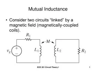
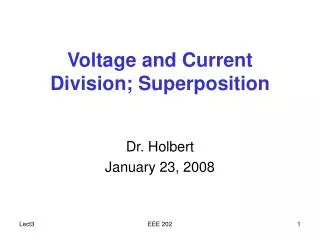
Voltage and Current Division; Superposition. Dr. Holbert January 23, 2008. I. R. R. + –. V S. R. Single Loop Circuit. The same current flows through each element of the circuit — the elements are in series We will consider circuits consisting of voltage sources and resistors. I R. I.

E N D
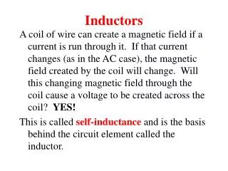
Voltage and Current Division; Superposition Dr. Holbert January 23, 2008 EEE 202
I R R + – VS R Single Loop Circuit • The same current flows through each element of the circuit—the elements are in series • We will consider circuits consisting of voltage sources and resistors EEE 202
I R I + – + R R I R – + – VS + N Total Resistors R I R – Solve for I • In terms of I, what is the voltage across each resistor? Make sure you get the polarity right! • To solve for I, apply KVL around the loop IR + IR + … + IR – VS = 0 I = VS / (N R) EEE 202
In General: Single Loop • The current i(t) is: • This approach works for any single loop circuit with voltage sources and resistors • Resistors in series EEE 202
+ + – – Voltage Division Consider two resistors in series with a voltage v(t) across them: R1 v1(t) – v(t) + R2 v2(t) EEE 202
In General: Voltage Division • Consider N resistors in series: • Source voltage(s) are divided between the resistors in direct proportion to their resistances EEE 202
+ I1 I2 I R1 R2 V – Two Resistors in Parallel How do we find I1 and I2? EEE 202
+ I1 I2 I R1 R2 V – Apply KCL with Ohm’s Law EEE 202
Equivalent Resistance If we wish to replace the two parallel resistors with a single resistor whose voltage-current relationship is the same, the equivalent resistor has a value of: Definition: Parallel - the elements share the same two end nodes EEE 202
Now to find I1 • This is the current divider formula • It tells us how to divide the current through parallel resistors EEE 202
+ I1 I2 I3 I R1 R2 R3 V – Three Resistors in Parallel I= I1 + I2 + I3 EEE 202
Solve for V EEE 202
Equivalent Resistance (Req) Which is the familiar equation for parallel resistors: EEE 202
Current Divider • This leads to a current divider equation for multiple parallel resistors • For 2 parallel resistors, it reduces to a simple form • Note this equation’s similarity to the voltage divider equation EEE 202
+ I1 I2 Is1 Is2 R1 R2 V – Example: More Than One Source How do we find I1 or I2? EEE 202
+ I1 I2 Is1 Is2 R1 R2 V – Apply KCL at the Top Node EEE 202
Multiple Current Sources • We find an equivalent current source by algebraically summing current sources • As before, we find an equivalent resistance • We find V as equivalent I times equivalent R • We then find any necessary currents using Ohm’s law EEE 202
In General: Current Division • Consider N resistors in parallel: • Special Case (2 resistors in parallel) EEE 202
Superposition “In any linear circuit containing multiple independent sources, the current or voltage at any point in the circuit may be calculated as the algebraic sum of the individual contributions of each source acting alone.” EEE 202
How to Apply Superposition • To find the contribution due to an individual independent source, zero out the other independent sources in the circuit • Voltage source short circuit • Current source open circuit • Solve the resulting circuit using your favorite technique(s) EEE 202
1kW 1kW 1kW 1kW 1kW 1kW + + + + – + – V1 + – + + – V2 V’out 1kW 1kW V’’out V1 Vout 1kW V2 – – – Superposition of Summing Circuit EEE 202
1kW 1kW 1kW 1kW + + + – + – V1 + V2 V’out 1kW 1kW V’’out – – Use of Superposition V’out = V1/3 V’’out = V2/3 Vout = V’out + V’’out = V1/3 + V2/3 EEE 202
Superposition Procedure • For each independent voltage and current source (repeat the following): • Replace the other independent voltage sources with a short circuit (i.e., V = 0). • Replace the other independent current sources with an open circuit (i.e., I = 0). Note: Dependent sources are not changed! • Calculate the contribution of this particular voltage or current source to the desired output parameter. 2. Algebraically sum the individual contributions (current and/or voltage) from each independent source. EEE 202
Class Examples • Drill Problems P2-2 & P2-4, P2-7, P2-1 & P2-3 EEE 202