Preliminary results from SPS collimator MDs
340 likes | 502 Vues
Preliminary results from SPS collimator MDs. LTC 27.10.04 R. Assmann for the collimation team. People involved in collimator design/construction/testing. This has been an outstanding team effort over the last 12 months! Work by:

Preliminary results from SPS collimator MDs
E N D
Presentation Transcript
Preliminary results from SPS collimator MDs LTC 27.10.04 R. Assmann for the collimation team
People involved in collimator design/construction/testing • This has been an outstanding team effort over the last 12 months! • Work by: O. Aberle, G. Arduini, R. Assmann, A. Bertarelli, T. Bohl, L. Bruno, H. Burkhardt, S. Calatroni, F. Caspers, E. Chiaveri, B. Dehning, A. Ferrari, E.B. Holzer, J.B. Jeanneret, L. Jensen, M. Jimenez, R. Jones, M. Jonker, T. Kroyer, M. Lamont, M. Mayer, E. Metral, R. Perret, L. Ponce, S. Redaelli, G. Robert-Demolaize, S. Roesler, F. Ruggiero, D. Schulte, H. Tsutsui, P. Sievers, R. Steinhagen, V. Vlachoudis, L. Vos, J. Wenninger, F. Zimmermann, ... • Not including work on LHC collimation design!
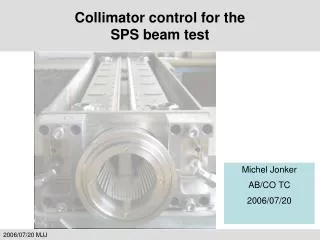
Goals of SPS Tests • SPS ring: Show that the LHC prototype collimator has the required functionality and properties (mechanical movements, tolerances, impedance, vacuum, loss maps, …). 2.TT40 extraction:Show that an LHC collimator jaw survives its expected maximum beam load without damage to jaw material nor metallic support nor cooling circuit (leak). Crucial project milestone Mechanical engineering(installation 18Aug04) Tolerances Prototype production Control and motorization Set-up of a single LHC collimator with beam (APC April 04)
Beam conditions • Beams prepared by G. Arduini, J. Wenninger and OP team • Low intensity MD: Monday Oct 11th Bunch population 1.1e11 p Number of bunches 1-16 Beam energy 270 GeV Emittance ~ 1 mm H beam size at collimator ~ 0.4 mm Beam orbit stability ~ 10 mm • High intensity MD: Monday Oct 18th Bunch population 1.1e11 p Number of bunches 288 Beam energy 270 GeV Emittance ~ 3.75 mm H beam size at collimator ~ 0.7 mm • Robustness test: Monday Oct 25th
Configuration BLM team Collimation team: Collimator in P5 of SPS BLM team: 8 downstream BLMs Together: 1 Hz DAQ and plotting in control room
Different issues • Functionality and basic collimator control • Set-up and beam-based alignment of jaw (includes BLM diagnostics) • Halo dynamics • Impedance and trapped modes • Heating of collimator • Vacuum and e-cloud (outgassing) • Effects on BPM’s and orbit feedback
1. Functionality: Mechanical movement and tolerances • Collimators moved in a FULLY operational way: no limits or unexpected difficulties encountered! • Closest gap of ~ 1 mm achieved with circulating beam! Mechanical tolerances and angular alignment at the ~ 100 mm level! Much smaller gaps than required in the 7 TeV LHC have been achieved with the LHC collimator prototype and circulating beam! • Knowledge of full collimator gap (excluding human math errors): Absolute ± 100 mm Reproducibility ± 20 mm Anti-collision settings 1.188/1.146/1.160 mm Gap known to 100 mm with excellent reproducibility (20 mm) over 16 h (motor setting reproducibility)! Some sensors useful others less useful: Reduce number of sensors!
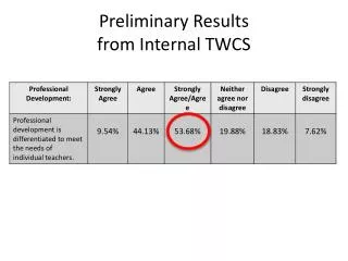
2a. Set-up and beam-based alignment of jaw Gap width Gap center First basic set-up (100 mm accuracy) within 50 min!
2b. Set-up and BBA: Typical BLM signal for move of jaw Observation of BLM signal tails: Up to 10-20 seconds in length BLM team: Many measurements Beam related true signal!
2c. Studies of BLM systematics Time L. Ponce et al
2d. Set-up and BBA: High precision set-up • LHC requirement: Center gap around beam with ~ 25 mm accuracy for nominal b* (beam-based alignment). • SPS beam: 120 h beam lifetime (de-bunched beam?) orbit stable to 5 mm ideal tuning conditions • Observation: Beam-based alignment ... ... to 100 mm is OK! ... to 50 mm is difficult! ... to 10-20 mm is impossible? • Understand effect to improve beam-based set-up!
3a. Halo dynamics: Re-shaping Collimator jaw Beam distribution After 10-20 seconds: New stable shape • Problem: Re-shaping of beam with collimator in!? • Edge 1 jaw 1 creates sharp edge and stays in! • Rectangular distribution close to edge unstable! • Particles in sharp edge diffuse and are lost! • No sharp edge for precise alignment of edge 2 jaw 1 or jaw 2! • Similar effects observed in ISR, SPS, ... No sharp edges!
3b. Measurement of repopulation rate – jaw positions Right jaw Dump beam on collimator 2.7 mm ≈ 6.5 s Left jaw G. Robert-Demolaize et al • Move from 7.7 mm (~ 19s) back and forth to 2.7 mm (~ 6.5s). • Wait different times in between. • Observe beam loss.
3c. Measurement of repopulation rate - BLM signals G. Robert-Demolaize et al DC coll at 6.5 s DC coll at 19 s G. Robert-Demolaize et al
3d. Measurement of repopulation rate – low intensity analysis G. Robert-Demolaize et al Shows how much beam diffuses out of sharp edge versus time!
3e. Measurement of repopulation rate – high intensity analysis G. Robert-Demolaize et al
3f. Beam distribution close to the edge after 30 seconds 1 mm 50 mm G. Robert-Demolaize et al
3g. DC beam loss versus collimation depth ~ 10 s ~ 20 s S. Redaelli et al More beam losses with collimator jaws further in: Enhanced diffusion rate?
4a. Impedance and trapped modes • Impedance is a limitation for the LHC collimators. • Impedance depends on collimator gap. • Measurement is simplified as impedance can controlled through gap. • Different measurements tried:Tune shifts, orbit kicks, trapped modes, growth rates, ...
Collimator MDs #2 – (some) BBQ results LARGE gap SMALL gap Collimator cycled between • 51 mm and 3.86 mm (5h04) • 51 mm and 2.86 mm (5h35) • 51 mm and 2.46 mm (5h43) • 51 mm and 2.06 mm (5h50) • 51 mm and 1.86 mm (5h58) Direct Diode Detection Base-Band Q-Measurement
Collimator MDs #2 – (some) BBQ results BBQ system 245 MHz system 245 MHz system confirms data (F. Caspers/T. Kroyer) Also: Standard tune measurments (H. Burkhardt) • Collimator cycled (at ca 4h33) between the gap of 51 mm and 2 mm. • Tune frequency was changing by 10 Hz, i.e. 2.310-4(frev) Direct Diode Detection Base-Band Q-Measurement
Collimator MDs #2 – (some) BBQ results Direct Diode Detection Base-Band Q-Measurement
4b: Trapped modes • Collimators were equipped with RF pickups to measure trapped modes. • Measurement with and without beam by F. Caspers and T. Kroyer. • Observation: • There are trapped modes. • They are excited by beam. • No effect on collimator temperature or beam stability observed. • Detailed analysis required. • Fritz has won a bottle of Champaign and 20 straws... F. Caspers & T. Kroyer
5. Heating of collimator (high intensity) No sign of problematic heating... Maximum increase 10 deg for closing gaps quickly!? No over- or under-design of collimator cooling...
6. Vacuum and e-cloud • No sign of vacuum pressure increase. • No sign of local e-cloud at the collimator.
7. Effects on BPM’s and orbit feedback • Scraping of up to 5e12 protons at 270 GeV. • No effect observed on downstream BPMs and overall orbit feedback (R. Steinhagen & J. Wenninger). • Orbit feedback stabilized to 10 mm orbit drifts. However, increased noise observed on BLM (equivalent to 10 mm jaw steps and consistent with BPM noise). FB ON FB ON
Robustness test in TT40 • Beam accident just before sending first beam to collimator. • Septum/power supply problem ( Jan). Safe extraction of nominal LHC beam for another trial? • Collimator in TT40 saw no beam (except showers from accident). • Concerns about collimator safety: • Lot’s of calculations and lab measurements We are convinced it will survive without damage (both jaw and water cooling circuit)! • We had vacuum/radiation protection/cooling water experts on stand-by in the control room for an eventually needed emergency intervention. • Was not needed for the collimator but was helpful for fast recovery of the SPS. • Try again the robustness test:We are convinced there will be no problem. However, there can always be a bad surprise Test now with SPS beam so we can still correct problems! If there is an unexpected problem it would be a real mess to only find it in the LHC!
Preliminary conclusions Collimator design has been validated successfully in beam operation: • Fully functional device with no significant hardware problems. • Real world performance provides knowledge base for possible savings: Reduce number of sensors to required minimal level (save budget). • Small gaps (smaller than in LHC) established with good accuracy and tolerances (circulating beam for 1 mm gap). • Impedance measurements confirm predictions: Phase 2 collimators are required for above 50% of nominal intensity (resources???). • Set-up and beam-based jaw alignment worked at intermediate precision: Need to advance quantitative understanding of halo dynamics for b* below ~ 1m with high precision jaw set-up (resources???). • Collimator design does not require any modifications (except maybe some material for absorbing trapped modes, if found dangerous). • Collimators will now be produced and we are convinced that phase 1 collimators will be robust and powerful tools for the LHC (robustness test should still be done)!