Download
1 / 37
470 likes | 848 Vues
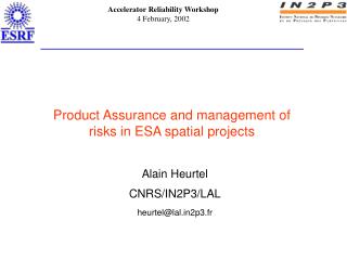
Product Assurance and management of risks in ESA spatial projects. Alain Heurtel CNRS/IN2P3 /LAL heurtel@lal.in2p3.fr. Plan Product Assurance and Product Assurance Plan Principle of the risks policy Application :The HFI of the satellite Planck Preliminary Risks Analysis

E N D
Product Assurance and management of risks in ESA spatial projects Alain Heurtel CNRS/IN2P3/LAL heurtel@lal.in2p3.fr
Plan • Product Assurance and Product Assurance Plan • Principle of the risks policy • Application :The HFI of the satellite Planck • Preliminary Risks Analysis • Reliability calculations • Definitions • The block diagram method • The failure rate determination • Examples • Critical Items List • Process FMECA • Conclusion Alain HEURTEL CNRS/IN2P3
Product Assurance • Main characteristics of spatial projects: • No possibility to repair in flight after launch, • Important vibrations during launch, • Necessity of cleanliness to avoid contamination redeposition in – flight. • Consequences: Obligation to master the risks by a reflection accompanying the Project from conception to launch. • This is the domain of « Product Assurance » As soon as the beginning of the feasibility phase, ESA imposes to draft the « Product Assurance Plan ». It will be up-graded along the project and presented to milestones reviews. Alain HEURTEL CNRS/IN2P3
The Product Assurance Plan (1/2) The Plan contains the guidelines of the general technical activities and methods foreseen by the Project to design, to build, to control, to test the instrument before integration. It is written by the Product Assurance Manager. Product Assurance Plan • Principles of selection • materials, • processes. Fabrication requirements : "Quality Assurance" Documentation management (Principles) Safety (Principles) Principles of reliability and risks management Configuration management (Principles) Cleanliness (Principles) Alain HEURTEL CNRS/IN2P3
The Product Assurance Plan (PAP) (2/2) • Product Assurance requirements are defined by the ESA ECSS documents (European Cooperation for Space Standardisation) : http://www.estec.esa.nl/ecss/(after authorization) • The PAP should be in agreement with these requirements. It is reviewed by ESA for approval. • The management of PA is made through a network of Local Product Assurance Managers (one for each sub-system). Alain HEURTEL CNRS/IN2P3
Principe of the risks policy How to master the risks? • To search for the risks: early, then continuously : Preliminary Risks Analysis : written at system level by PAM. • To classify them according to a hierarchical system considering their seriousness : Critical Items List : written by each team and coordinated by the PAM. • To accept them or to treat them : Reliability Analysis : performed by the PAM, in parallel. • To analyse the consequences on the Instrument: Failure Mode Effect and Critical Analysis (Process FMECA) . Probability Non exploitable domain • Protection 0 Prevention Seriousness Alain HEURTEL CNRS/IN2P3
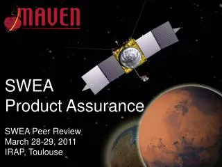
The High Frequency (HFI) Instrument of Planck Planck "cornerstone of ESA programme" • Principle :2 surveys of the sky by detection of the cosmic background (14 months). • Technology : Detection in mm range by horns and bolometers at 100mK ± 5mK. 280kg. 3 coolers : Liquid H2 and liquid He are obtained by close loops. Dilution of 3He in 4He cryostat in an open loop from boarded spheres of gas. Satellised at L2 (1.5Mkm / the earth). • Management : International consortium of 250 people and 11 Institutes managed by Institut d’Astrophysique Spatiale (Orsay). Participation of 3 labs. of IN2P3 (LAL, PCC, ISN). ESA provides one Alcatel plate-form and launch in 2007 by Ariane V. • Budget : Provisional budget of 100ME, including launch. French part provided by the CNES. Alain HEURTEL CNRS/IN2P3
Primary mirror (1,5m in Ø) Planck telescope Straylight shield LFI and HFI instruments Thermal shields Interface with Herschel Service Module screen Service module Solar cells The High Frequency (HFI) Instrument of Planck Panneaux solaires Alain HEURTEL CNRS/IN2P3
The Preliminary Risks Analysis (1/3) • 1st step • Objectives : • Identification of the basic functional constituents of the instrument by functional analysis, • Early identification of the possible failure modes, • Timely design improvements to reduce the number of critical items and reduce risks. • Expected results : • Forces a functional decomposition, • Provides an early visibility on the adequacy of fault tolerances requirements, • Guides the design in redundancy possibilities, • Provides an early understanding of the degraded modes existing after one failure, and safety hazards. Alain HEURTEL CNRS/IN2P3
The Preliminary Risks Analysis (2/3) • ESA failure effect severity : • Ex : Possibilities of signal degradation along the functional chain. (coolers are considered as slaves devices at nominal temperature) Alain HEURTEL CNRS/IN2P3
Preliminary Risks Analysis : (3/3) worksheet Alain HEURTEL CNRS/IN2P3
Reliability : From evaluation to optimisation • 2nd step ( during the design phase) • Objective : To evaluate the different possible architectures by comparison of their performances by statistic data. • Conditions : The method must be sufficiently rich to describe the functioning of the product, but the simplest possible to be evaluated by the project. • Methods of evaluation : • The universal generic method does not exist. • Limits : • Abusive utilization of quantitative analysis to justify risks which are difficult to measure, • Tendency to rejection of all quantification. Can lead to incoherent architectures. • For HFI we have used the RELIABLITY BLOCK DIAGRAM method.Others are complementary: Fault tree, Markov graph, Petri boxes etc… Alain HEURTEL CNRS/IN2P3
l( t ) OK KO Bath tube Youth l(t) Beginning of operation Wear t Useful life Reliability : Definitions • Failure rate :l • Reliability R. lis the probability of failure of system between t and t+dt when dt 0, with the item running at t. (Reliable at t) • Life curve : If l is constant during the useful life. R(t)=exp(-lt) 0 Alain HEURTEL CNRS/IN2P3
Reliability : Definitions (Cont'd) Failure rate lis often expressed in fits (10-9failure/hour) Exp : Processor module l 1000 fits R(10y) = 0.92 • Failure : F(t) = 1 - R(t) • Associated definitions : • MTTF : Mean Time To Failures (in hours) for a repairable system = 1/l • MTBF Mean Time Before Failure • If system not repairable MTTF= MTBF R(t) = exp(-1) = 0.37 MTBF is the time the component has a probability of failure of 0.63. Alain HEURTEL CNRS/IN2P3
l1 l2 li l = l l1 l2 li Reliability : The Bloc Diagram Method (BDM) (1/9) • A chain of elements (mechanics or electronics) simultaneously supplied is figured by a combination of elements in serial or parallel. • Serial diagram: Loss of the chain if 1 element fails • Parallel diagram: • Generalisationof the method : • Can be enriched by conditional probabilities. • If possibilities of redundancy exist, the different states of the system can be represented by a matrix (Markovian treatment). (Only if transition rates are constant : not for wear) This method is used in CNES to modelise the essential of a satellite å R=(Ri) i Loss of the chain if all elements fail R=1-[(1-Ri)] Alain HEURTEL CNRS/IN2P3
l1 l2 l1/10 l2/10 Reliability : The Block Diagram Method (2/9) • Kinds of redundancy : • Active M among N elements : All N elements function simultaneously, • Passive M among N : M-N elements are spare elements waiting for failure of active elements, • Cold/warm : characterises the energytical state of an element. (loff=lon/10), • Cross strapping : Sharing in elements individually redundated. Complex, slow down, can introduce risks in spite of electronics switches use. • Recent enrichment of the symbolic : • Repairing rate, • Rate of use for active elements, • Incorporation of spare resources when redundancy is active. Alain HEURTEL CNRS/IN2P3
Reliability : The Block Diagram Method (3/9) • Ex 1: Functional electronics chainrepresentation: DPU Alain HEURTEL CNRS/IN2P3
DPU Processor DC/DC Converter I/F S/C I/F 01k I/F 4KCDE I/F REU To S/C 300 fits 300 fits 1000 fits 500 fits 300 fits 300 fits serial RDPU=0.9538 Reliability : The Block Diagram Method (4/9) • Ex 1 (Cont'd) : Digital ProcessingUnit (DPU) chain: Block Diagram representation: DPU All supplied elements are considered in serial I/F REU DPU Processor I/F S/C DC-DC Converter To REU Distrib I/F 0.1 K I/F 4K CDE Problem : How to obtain l ? Alain HEURTEL CNRS/IN2P3
Reliability : BDM (5/9) - l determination - • Conventional methods : based on observable failures with fits of empirical models. Old norms :reflect the real failure rates but they are not always regularly revisited. • MILHBK217 FDOD for military and Hi-Rel components only. • SRDF (EdF) for nuclear industry, • RDF 93 (CNET) for electronics. • New vast domain of experimentation and investigation based on : • Quality tests and accelerated tries (life tests and thermal cycling, fatigue etc..), with application of acceleration factors. • Bayesian methods: combination of statistic data based on total probabilities of different causes, with a previous a priori knowledge : (return of experiences, empirical assessments, experts advices). Recent norms : returns of experiments and accelerated methods. • RDF 99 UTE 80810 (CNET) • RAC 97 (Reliability Analysis Centre) • PRISM RAC (US) for mechanisms • ESA PSS-01-302 for mechanics and electronics. Alain HEURTEL CNRS/IN2P3
Reliability : The Bloc Diagram Method (6/9) • Ex 1:(cont'd) R total=0.8676 R total=0.94043 With cross strapping between DPU and REU = 0.94212 - Clearly : Important increase in reliability if redundancy : ~7% for 2 years. - Only relative differences are significant. Alain HEURTEL CNRS/IN2P3
Reliability: The Bloc Diagram Method (7/9) • Ex 2: 3He and 4He distribution chains from spheres at RT Alain HEURTEL CNRS/IN2P3
Reliability: The Bloc Diagram Method (8/9) • Reliability of the chain with redundanced element gives 0.966 (1.2% gain). Limited by weak point : Pressure reducer, • For mechanics : • Studies are complex: Several possibilities of failure exist for valves depending on applied pressure, mode of functioning (untimely and/or loss of function). • Less data available than for electronics. • Influence of functioning rate. Are the failure rates applicable when valves are actuated only 2 or 3 times during the mission instead of each hour? • This domain of failure physics is in expansion : • Modelling of extrinsic failure. • Priority : Refine models leading to l determination. Alain HEURTEL CNRS/IN2P3
Reliability: The Bloc Diagram Method (9/9) • Conclusion: • The BDM allowed us to modelise a large part of HFI, • The evaluations are still delicate for domains out of electronics, • Quantitative results should be used in relative. • Tools : • MIL STRESS Item Software • REFLEX Reflex Software Corporation • FIABEX of CEP System • CARE distributed by Ligeron • SELECT from RAC • SUPERCAB+ from Cabinnovation (Supported by the CNES). http://www.cabinnovation.fr • Information : Centres de Compétences Techniques CCT (CNES) : Contact : Andre.Cabarbaye@cnes.frRoland.Laulheret@cnes.fr Alain HEURTEL CNRS/IN2P3
Critical Items List (CIL) (1/4) • 3rd step of the ESA risk management policy. • Definition of a critical element : « All element (hardware or software) or an elementary process, which may particularly endanger the development or mission success. It offers a reduced degree of confidence about their own performances in operation, if not previously "adequately" controlled on ground, during manufactures and tests phases ». • Applicable for : • Not yet developed item, • Items that cannot be controlled for the relevant properties without degradation, • Items whose functionality can no longer tested after integration as they may fail during acceptance testing unnoticed, • Items provided by inexperienced institutes, • Items located at interfaces. Alain HEURTEL CNRS/IN2P3
Critical Items List: (2/4) • The actions to be taken : • Render them non-critical, • Control the criticality by dedicated actions. • Methodology : • On demand of the Project, the lists of Critical Items and proposed actions to reduce them are written by the different groups, • They are centralised at Project level by the Product Assurance Manager, • Each group is responsible for its actions of risk reduction. • Each group shall inform the Project when the action is closed, for validation. • Official diffusion : The actualised List is sent to each group and to ESA with the Monthly Report. Alain HEURTEL CNRS/IN2P3
Critical Items List (CIL) (3/4) • Format of the list Alain HEURTEL CNRS/IN2P3
Critical Items List: Ex.of worksheet (4/4) Alain HEURTEL CNRS/IN2P3
Process Failure Mode Effects and Critical Analysis (FMECA) (1/8) • 4th step of action in risk reduction. • Aim:The instrument should keep the same performance along the mission. So, necessityto perform the analyse of possible degradation modes in flight, as soon as the design phase. • Method : • Detailed review of possibilities of failures (on time degradation and/or brutal failures) of each part of equipment and relevant interfaces. • Determination of the damages and interferences on other sub-systems in terms of severity, by the mean of analyses : • made at system level for the instrument, • made at component level for the interfaces with the spacecraft, • applicable to all functions and all units : For on-board software special analysis is foreseen as soon as soft begins to be written. • Result : • Modifications and recommendations are proposed to increase the reliability using to procedures (see example later-on). • Auto-check of the whole instrument before fabrication Alain HEURTEL CNRS/IN2P3
Process Failure Mode Effects and Critical Analysis (FMECA) (2/8) • The criteria : "severity" • Rubrics of worksheets are different along the position of the element in the chain : Alain HEURTEL CNRS/IN2P3
Process FMECA (3/8) • In practice : • To be efficient FMECA should be practised in each group in charge of sub-system and conducted by a cognizant manager, • All actors involved in a sub-system should participate to the analyses meetings, • All functions are successively analysed with their interfaces, • Worksheets are fulfilled during the meeting, • Manager gathers FMECA sheets and write the recommendations. Alain HEURTEL CNRS/IN2P3
Process FMECA (4/8) • Example: Precedent valve box Alain HEURTEL CNRS/IN2P3
Process FMECA (5/8) • Ex : For the DPU (Data Processing Unit) Alain HEURTEL CNRS/IN2P3
Process FMECA (6/8) • Follow-on actions: • Case (a) : Ex. of recommendation for Data Processing Unit (DPU). Alain HEURTEL CNRS/IN2P3
Process FMECA (7/8) • Follow-on actions (cont'd): • Case (b) : rejection of recommendation by the S/S team. • Rejected with the rationale for rejection. • Case (c) : alternative recommendation from the S/S team. • Action and a due date for the implementation, • The modified situation shall be treated on the same process FMECA worksheet to identify the improvements. Alain HEURTEL CNRS/IN2P3
Process FMECA (8/8) • 3 other documents will be issued from the FMECA • The Summary Failure Detection Isolation and Recovery (FDIR). How to manage the different potentialities of redundancies . • TheWorst Case Analysis on critical interfaces parameters, (for electronic components). For HFI, the ESA asked analyses is only the verification of margins. In theory, it would be done by analytical analysis of the transfer function of the device (Monte Carlo simulation). Can be a complex and heavy analysis. • Hardware Software Interaction Analysis (HSIA). • The 2 first documents should be presented one month before the PDR (Preliminary Design Review) to be evaluated by ESA. They can condition the passage in the phase of fabrication. Alain HEURTEL CNRS/IN2P3
Conclusion (1/2) • The ESA policy in matter of risks is defined very early in the Project by the Product Assurance Plan based on the ECSS requirements. • The methods, complementary each other, allowing to identify and to treat potential risks in terms of prevention and protection during the design phase are : • Preliminary Risks Analysis at system level: Determination of the basic functional constituents and of their failure mode. • Reliability analysis: Can size correctly the systems in function of needs. The Block Diagram Method, used for Planck, gives assessments on reliability for the whole instrument. • Critical Item List: For elements or processes which can endanger the mission success. • The Process FMECA: To determine the possible modes of degradation in functioning and their propagation. Alain HEURTEL CNRS/IN2P3
Conclusion (2/2) • ESA Product Assurance policy entails an inter-active reflection and a continuous feed-back through the different teams of the project during the design phase. This risk policy is now mandatory in all spatial projects : final gained time is estimated by previous experiences, at a minimum 10 times time spent to realize these analysis. Alain HEURTEL CNRS/IN2P3