Basic Electronics
Basic Electronics.

Basic Electronics
E N D
Presentation Transcript
Basic Electronics Course Standard Parts List Quantity Part Description Part Number Jamco Number Cost (2004) 1 Mastech Mulitmeter M830B 220855CR $9.95 1 Solderless Breadboards JE24 20757CR $9.95 1 Jumper Wires* JE27 77825CR $12.95 1 9V Battery Holder BH-9V-A 216426CR $0.79 1 1.5V Battery Holder BH-311-2A 216071CR $0.69 1 100 ohm ** 29946CR 1 200 ohm 59424CR 1 330 ohm 30867CR 2 1000 ohm 29663CR 1 2.2K ohm 30314CR 2 4.7k ohm 31026CR 1 10K ohm 29911CR 1 100K ohm 29997CR 1 100uF Electrolytic Cap 94431CR $0.09 1 Diode 1N914 179207CR $0.05 1 Zener Diode 1N4732A 36089CR $0.06 1 Transistor 2N3604 178597CR $0.09 1 LED LH2040 94529CR $0.19 * More jumpers than needed for one student, can be shared to reduce costs ** Individual components are often sold is quantity, quantity purchase can be shared between students to reduce costs.
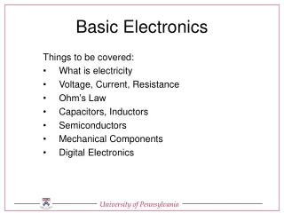
Basic Electronics for the New Ham (Outline) • The Components of Electricity • Volt-Ohm-Meter Basics (Measuring Electricity) • Circuit Diagrams Basics (Electronic Roadmaps) • The Resistor • Ohm’s Law • The Capacitor • The Inductor • The Diode • The Transistor (Electronic Valves)
The Components of Electricity • Voltage • Current • Resistance • Types of Current: AC and DC • Circuits • Close • Open • Short
Water flowing through a hose is a good way to look at electricity Water is like Electrons in a wire (flowing electrons is called Current) Pressureis the force pushing water through a hose – Voltage is the force pushing electrons through a wire Friction against the hole walls slows the flow of water – Resistance is the force that slows the flow of electrons Voltage, Current, and Resistance
Types of Current • There are 2 types of current • The type is determined only by the direction the current flows through a conductor • Direct Current (DC) • Flows in only one direction negative toward positive pole of source • Alternating Current (AC) • Flows back and forth because the poles of the source alternate between positive and negative
Circuits • A circuit is a path for current to flow • Three basic kinds of circuits • Open – the path is broken and interrupts current flow • Close – the path is complete and current flows were it is intended • Short – the path is corrupted in some way and current does not flow were it is intended
Common Functions Voltage AC/DC Ranges Current AC/DC Ranges Resistance Ranges Continuity Semi-conductor Performance Transistors Diodes Capacitance Volt-Ohm-Meter Basics(Measuring Electricity)
Volt-Ohm-Meter Basics Meter Reading Digits DC Voltage Scales AC Voltage Scales Function Selection Probes
Volt-Ohm-Meter Basics DC Current (low) DC Current (high) Resistance Transistor Checker Diode Checker
Measuring voltage Voltage type Scaling Safety Physical (personal) Equipment Measuring current Current type Scaling Safety Physical (personal) Equipment Measuring resistance Scaling Volt-Ohm-Meter Basics(Measuring Electricity)
Measuring voltage • Voltage type – DC and AC • When measuring voltage, the meter probes are placed across the voltage source. • The VOM uses two separate functions and ranges to measure DC and AC. • Because AC is a constantly changing wave form, measuring AC voltages is not a simple matter. • This VOM measures pseudo-RMS voltages
Measuring voltage • Meter Set-up • Scale set to highest predictable • Probes into right jacks • Note voltage polarity +
Measuring Voltage • Set-up VOM on 600V DC Scale • Touch red probe to (+) • Touch black probe to (–) • Read voltage to nearest 1 volt
Measuring Voltage • Now touch the red probe to (-) • Touch the black probe to (+) • Read voltage to nearest 1 volt, note the minus sign that signifies a negative voltage
Measuring Voltage • Set-up VOM on 200V DC Scale • Touch red probe to (+) • Touch black probe to (–) • Read voltage to nearest .1 volt
Measuring Voltage • Set-up VOM on 20V DC Scale • Touch red probe to (+) • Touch black probe to (–) • Read voltage to nearest .01 volt
Measuring Voltage • Set-up VOM on 20V DC Scale • Touch red probe to (+) • Touch black probe to (–) • Using a 1.5 volt battery - read voltage to nearest .01 volt
Measuring Voltage • Set-up VOM on 2000mV DC Scale • This scale is reading 2000 milli-volts (or 2 volts) • Touch red probe to (+) • Touch black probe to (–) • Using a 1.5 volt battery - read voltage to nearest .001 volt
Measuring Voltage • Set-up VOM on 2000m V DC Scale • Touch red probe to (+) • Touch black probe to (–) • Using a 9 volt battery • This is clearly an over-voltage situation, note the reading.
Measuring Voltage - Safety • When measuring voltage, the voltage being measured is exposed to the operator and flowing through the probes. Be cautious, be attentive, watch what you touch! • The probes have sharp points so that you can make precise contacts. Use the protective shields when probes not in use. • Observe the meter maximum limits for voltage and current. Fuses are a last resort protection feature. If you blow a fuse, you made a mistake!
Measuring Current • There is greatest potential for meter damage when measuring current than any other function. • Just as in voltage, there is two kinds of current associated with the voltage, AC and DC • This meter will only measure DC, more expensive meters will measure both currents • To measure current, the VOM must be inserted into the circuit so that the current flows through the meter.
Measuring Current • There are two current ranges, high – up to 10 amps, and low – 200 milliamps (.2 amps) and below. • Internal fuses provide some meter protection for over current situations. • Because there is such a wide range of current scales, there are two physical probe jacks for the two ranges • This allows for better protection, a hardy fuse to handle up to 10 amps of current and a more fragile fuse to protect the sensitive circuits needed to measure small currents.
Measuring Current • CAUTION!!!!!!! There must be some resistance in the circuit or the current flow through the circuit will be the maximum the source will produce, AND THIS CURRENT LEVEL COULD DAMAGETHE VOM! • In other words, DO NOT CONNECT THE VOM PROBES DIRECTLY ACROSS THE BATTERY POLES IN THE CURRENT MEASURMENT FUNCTION!
Measuring Current • We will be using some concepts during the current measurement exercises that will be covered in more detail later, so be patient, it will all come together in the end. • In the following exercises you will use various resistors to limit the current flow in a simple circuit.
Measuring CurrentBasic Circuit VOM - + Resistor Battery
First Current Measurement • Set up the circuit using a 100 ohm resistor (brown, black, brown). • Connect a wire to the + power source, connect another wire to the top end of the resistor (the non grounded end). • Set VOM current scale to 200m. • Without connecting the battery, practice touching the VOM probes to the exposed wire ends.
First Current Measurement • Connect the battery. • With the VOM set to the 200m current scale, touch the black lead to the wire hooked to the high side of the resistor. • Touch the red lead to the lead coming from the + side of the battery. • Note the VOM reading.
First Current Measurement • Now reverse the VOM leads and note the reading.
First Current Measurement • Return the VOM leads so that the red is connected to the battery. • Change the VOM current ranges down and note the display readings • What is the best range for measuring the current from a 9 volt source through a 100 ohm resistor? 200m Range 20m Range
Measuring Current • Wire the circuit with a 1k ohm resistor (brown, black, red). • Measure current with 200m range.
Measuring Current • What is the best range to measure the current through a 1 k resistor? 200m 20m 2000u
Measuring Current • Wire the circuit with a 10 k ohm resistor (brown, black, orange). • Measure current with the 2000u range.
Measuring Current • What is the best range to use to measure the current through a 10 k ohm resistor at 9 volts? 2000u 200u
Measuring Current • Wire the circuit with a 100 k ohm resistor (brown, black, yellow). • Begin with the 2000m range, and measure the current at each range. • What is the best range to use to measure the current trough a 100 k ohm resistor at 9 volts?
Measuring Resistance • When the VOM is used to measure resistance, what actually is measured is a small voltage and current applied to the component. • There are 5 ranges, an out of resistance reading will indicate a single 1 digit. Remember k means multiply the reading by 1000. • Operating voltages should be removed from the component under test or you could damage the VOM at worst, or the reading could be false at best.
Measuring Resistance • Disconnect the battery from the board, remember to measure resistance the circuit should be un-powered. • Put the 100 ohm resistor in place, no additional wires are required. • Select the 200 range and touch the probe leads to either side of the resistor.
Measuring Resistance • Now reverse the probe leads and observe the reading. • Any difference?
Measuring Resistance 2000 • Now using the 100 ohm resistor, measure the resistance using each of the other ranges. • Note that the resolution of the reading decreases as the maximum ohm reading increases, down to the point where it is difficult to get a good resistance reading. 20k 200k 2000k
Measuring Resistance • Now use the 1k ohm resistor and the 200 range. • Explain the reading you observe. • Find the appropriate range to measuring 1,000 ohms (1k). 200 2000
Measuring Resistance • Now use the 10k and the 100k resistor. • First determine the appropriate range to use for each resistor. • Second make the resistance measurements • Third, using higher ranges predict the reading and confirm your prediction by taking the measurements
Measuring Resistance • Just for fun, use the VOM to measure the resistance offered your different body parts. • The voltage and current used by the VOM is not dangerous. • Discuss your observations and how your measurement techniques could influence the readings you get from the VOM.
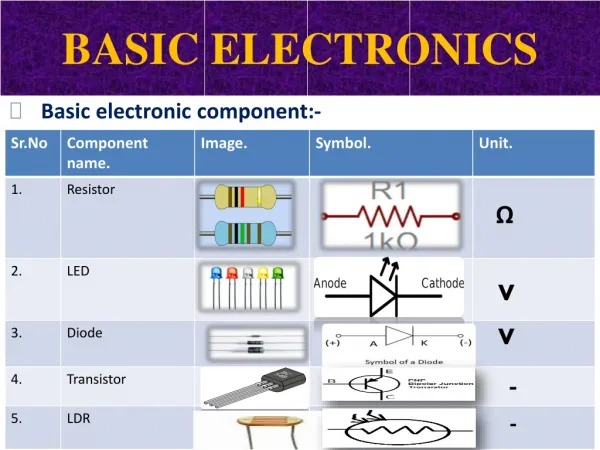
Circuit Diagrams Basics (Electronic Roadmaps) • Component Representations • Resistor • Ground • Capacitor • Inductor • Diode • Transistor • Integrated circuit • Miscellaneous