Download
1 / 13
130 likes | 277 Vues
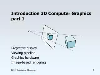
Introduction to 3D computer graphics part 2. Viewing pipeline Multi-processor implementation GPU architecture GPU algorithms. fragment/ pixel processing. geometry processing. CPU. 1 M polygons/s. 500 Mflops. 100 Mpix/s. 5000 Mips. Viewing pipeline. model from database.

E N D
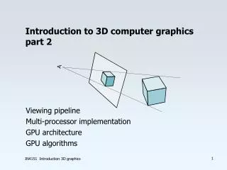
Introduction to 3D computer graphics part 2 Viewing pipeline Multi-processor implementation GPU architecture GPU algorithms IN4151 Introduction 3D graphics
fragment/ pixel processing geometry processing CPU 1 M polygons/s 500 Mflops 100 Mpix/s 5000 Mips Viewing pipeline model from database approximate curved surfaces by polygons light intensity clipping window to viewport transformation viewingtransformation perspective divide edge processing scan-conversion span interpolation depth buffer test texture mapping area summing r,g,b, z, a-buf IN4151 Introduction 3D graphics
Viewing transformations Shading Clipping Perspective projection Viewport transformations P P FIFO FB P P P H P P buffer P M D/A Load balancing and bottlenecks Span interpolation Depth testing Texture mapping Alpha blending Pipeline is good for geometric processing (#vertices) Farm is better for scanline and pixel processing (#pixels) Access to frame buffer is now bottleneck IN4151 Introduction 3D graphics
P FB-R P FB-G P H M D/A P FB FB-B P P P P FB-Z P P P P M D/A P P P P P P P P P P P P P P H H P P Distributed frame buffers • Distribution for R,G,B and Z • Distribution by image subdivision IN4151 Introduction 3D graphics
1 : 1,2,3,4,17,18, .. 2 : 5,6,7,8,21,22, .. 3 : 9,10,11,12,25, .. 4 : 13,14,15,16,29, .. 5 : 65,66, ... 6 : .. 1 2 3 4 5 6 7 8 9 10 11 12 13 14 15 16 1 : 1,2,3,4,5,6,... 17,18,19,.. .... .... 2 : 33,34,35,... .... . . . . . . . . . . . . . . . . . . 1 : 1,5,9,13, 65, ... . . . . . . . . . . . . . . . . . . 2 : 2,6,10,14, ... . . . . . . . . . 1 2 3 4 3 : 3,7,11,15, ... . . . . . . . . . 5 6 7 8 . . . . . . . . . 4 : 4,8,12,16, ... . . . . . . . . . 9 10 11 12 5 : 17,21,25,29, ... . . . . . . . . . 13 14 15 16 . . . . . . . . . 6 : 18,22,26, ... 7 : ... Frame buffer distributions • Segmented • Coherence • No load balancing • Interlaced • Scan-line coherence • Better load balancing • Interleaved • No coherence • Optimal balance IN4151 Introduction 3D graphics
. . . . . . . . . . . . . . . . . . . . . . . . . . . . . . . . . . . . scan conversion geometry raster display subsystem subsystem subsystem subsystem SP x IE IE IE IE VP y SP IE IE IE IE z VP GA GE GE GE r SP GE PP IE IE IE IE VP g SP b IE IE IE IE VP a SP processors IE IE IE IE screen VP geometric accelerator geometric edge polygon video processors image engines engines processors processor +VRAM span processors Render architecture interleaved frame buffer Silicon Graphics IRIS 1988 100.000 polygons/s Access to texture memory is bottleneck IN4151 Introduction 3D graphics
GPU: vertex and fragment/pixel shaders • PC-graphics card • Game industry • 4-16 processors parallel • SIMD machine • Larger texture memory • Multiple passes • Programmable vertex operations transform, lighting polygon memory rasterization color, texture interpolation texture memory pixel operations depth compare, alpha test, blending, filtering frame buffer IN4151 Introduction 3D graphics
GPU processing / programming • Bump mapping, shadow map, environment map • BRDF shading, image based rendering • Image processing, filtering, segmentation • Use texture memory as internal memory • Map functions to tables • Some limitations: source cannot be sink • Limited number of indirections • Getting data back from the graphics card is slow IN4151 Introduction 3D graphics
Bump mapping Pertubate normal as a function of bump map IN4151 Introduction 3D graphics
Shadows light source Alternative: shadow volumes shadow map image IN4151 Introduction 3D graphics
Environment mapping • Environment map represents incoming radiance for center point • Can be stored in spherical map or cube • Reflection is look-up in map • Approximation to ray tracing! IN4151 Introduction 3D graphics
Diffuse environment shading • Need integration over environment map • For diffuse reflection scaled by cosinus • Index in filtered versions of map received radiance is function of accessability specular reflection diffuse reflection ambient occlusion IN4151 Introduction 3D graphics
Conclusions • Viewing pipeline for polygon rendering is still alive but real-time ray tracing is approaching • GPU programming is powerful tool: volume rendering, physically-based modeling, dynamics, etc. IN4151 Introduction 3D graphics