Introduction to 3D Game Engines: Basics of Rendering, Animation, and AI Systems
460 likes | 605 Vues
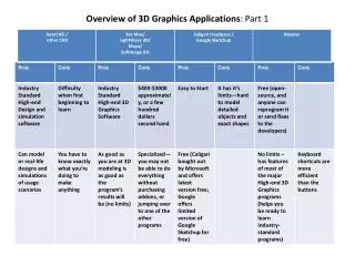
This guide provides a comprehensive overview of the fundamentals of 3D game engines. It explores the core components, including the 3D engine responsible for data rendering, animation systems for motion and physical interactions, and AI algorithms that enhance gameplay. Key topics like input systems, collision detection, and viewing pipelines are discussed, revealing how these elements interact within the game development pipeline. Gain insights into the complex relationships between physics, animation, and AI for creating engaging 3D experiences.

Introduction to 3D Game Engines: Basics of Rendering, Animation, and AI Systems
E N D
Presentation Transcript
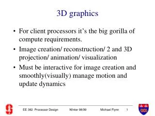
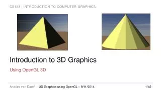
3D Graphics IntroductionPart 1 CIS 488/588 Bruce R. Maxim UM-Dearborn
3D Game Engine - 1 • 3D Engine • Software that processes the 3D world data structures and renders them from camera’s viewpoint (it does not do physics processing) • Game Engine • Controlling module that sends commands to all subsystems (calls the 3D Engine - not part of it)
3D Game Engine - 3 • Input System and Networking • Keep game separate from networking module (not part of 3D engine, AI, or physics) • Network support for 3D games must be designed early in the development cycle • Animation System • Simple Motion • Complex Animation • Physically-based Animation
Simple Motion • Basic translation and rotation of game objects • Might be tied to AI if objects need to move as units and physics to determine if movement is possible or not • Where to put the knowledge depends on the complexity of the game itself
Complex Animation • Implies the existence of articulated-hierarchical objects with links that must move in relation to each other (e.g. robot tank with an upper body moving turret) • Could be done by blitting frames from meshes • Can be done with motion data (e.g. BioVision) - similar to midi philosophy, link movement are scripted in relation to each other for independent playback – problem is where to place check for feedback
Physically-Based Animation • The laws of physics control all movement • For example fighting moves are pre-recorded motion capture data which is fed into the physically-based animation system that controls the physics models that perform the animation • The physically-based animation, animation, and physics systems are intimately connected (but not the 3D engine that only renders the polygon list without knowing how it was created)
3D Game Engine - 4 • Collision Detection and Navigation • May be the only physics system needed for simple game (feedbacks to AI and animation systems) • Physics Engine • Friction forces and acceleration • Elastic collision detection and response • Linear momentum transfer • Has nothing to do with 3D visual representation (though it does need to be tied in to the AI and animation systems)
3D Game Engine - 5 • AI System • All AI algorithms become harder to implement in 3D than in 2D • Usually tied to the animation and physics systems • 3D Model and Imagery Database • 3D meshes for objects • 2D texture maps and light maps • Motion and animation data • Game map data
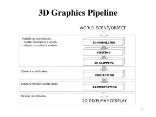
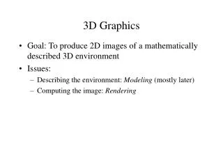
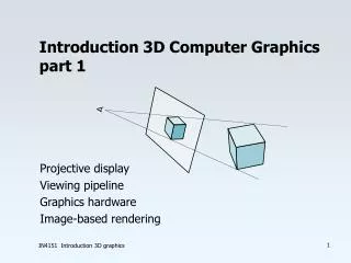
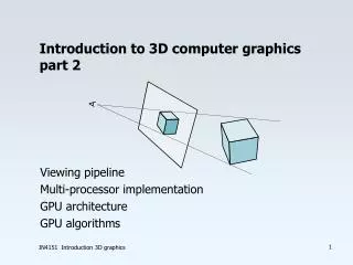
3D Viewing Pipeline • Model (local) coordinates • World coordinates • Camera coordinates • Perspective coordinates • Screen coordinates
Model (local) Coordinates • Coordinates assuming the center of object is centered at (0,0,0) or some other point • Convention might call for “front” pointing in z+ axis direction and “top” pointing in y+ axis direction • Alternatively the longest object axis can be aligned with z+ and the second longest object axis can be aligned with y+ • Model all objects using the same scale and adjust the scale during rendering if needed
World Coordinates • Actual coordinates in virtual world • Need to keep unit in mind (affects storage and speed of traversal at 30 fps) • To translate from model coordinates to world coordinates is done by translating the object | 1 0 0 0 | Twm = | 0 1 0 0 | | 0 0 1 0 | | x y z 1 |
Camera Coordinates • Camera coordinates • In 3D games the camera moves around • The camera is placed at (cam_x, cam_y, cam_z) pointed in direction (pitch,yaw,roll) • Field of view parameters define define what can be seen in the horizontal and vertical directions • To simulate human vision 110-120 degrees horizontally and < 90 degrees vertically • The 3D viewing frustrum is used to describe these relationships
Viewing Frustrum • Objects closer than the near_z clipping plane or farther than the far_z clipping plane are not rendered • The side planes are also used to clip the object that are to be rendered, with a 90% viewing volume each side plane is 45% to the view direction with equations |x|=z and |y|=z • To pretend the camera is at (0,0,0) and looking down the z+ axis requires a transformation (translate then rotate)
World to Camera - 1 • Translation step using Tcam-1 | 1 0 0 0 | [xw yw zw 1] * | 0 1 0 0 | = | 0 0 1 0 | | -cam_x –cam_y –cam_z 1 | = [xw-cam_x yw-cam_yzw-camz 1 ]
World to Camera - 2 • Rotation Rcamx-1 | 1 0 0 0 | | 0 cos(-ang_x) sin(-ang_x) 0 | | 0 –sin(-ang_x) cos(-ang_x) 0 | | 0 0 0 1 | • Rotation Rcamy-1 |cos(-ang_y) 0 -sin(-ang_y) 0 | | 0 1 0 0 | |sin(-ang_y) 0 cos(-ang_y) 0 | | 0 0 0 1 |
World to Camera - 2 • Rotation Rcamz-1 | cos(-ang_z) sin(-ang_z) 0 0 | |-sin(-ang_z) cos(-ang_z) 0 0 | | 0 0 1 0 | | 0 0 0 1 | • The complete transformation is Twc = Tcam-1 * Rcamy-1 *Rcamx-1 *Rcamz-1
Gimbal Lock • Occurs when one axis is rotated to the point that it becomes aligned with another and further rotation results in no movement at all • For example if the x-axis is rotated 90 degrees it could align with the y-axis so that rotating around the x-axis has no effect
Hidden Surface Removal • How do you know which objects are visible to camera before you so they are not transformed or rendered? • Commonly used techniques • Back-face removal • Bounding spheres test
Back-Face Removal - 1 • Step 1: • Remove all polygons outside of viewing frustum • Step 2: • If the dot product of the view vector and the surface normal is > 0, it is facing the viewer. • Remove all polygons that are facing away from the viewer.
Back-Face Removal - 2 • Step 3: • Draw the visible faces in an order so the object looks right. • Note: • Surface normal = cross product of two co-planar edges. • View vector from normal point to viewpoint
Bounding Sphere Test –1 • Can be used before back-face removal to discard entire objects all at once • This test only works if you have object partitioned in convex areas, won’t work for a game world composed of a single mesh • The idea is to create a bounding sphere around each object and then transform Twc the center of each sphere and see if the entire sphere is outside the viewing frustrum
Bounding Sphere Test – 2 • If none of the points p1-p5 is in the viewing frustrum the object can not be visible, the general test for point p(x,y,z) is outside if ((z > far_z) || (z < near_z) || // z-axis (fabs(x) < z)|| //x-z plane (fabs(y) < z)) //y-z plane { // point not in viewing frustrum }
Bounding Sphere Test – 3 • It is important to note that just because a portion of the bounding sphere is inside the viewing frustrum there is no guarantee that any portion of the object is visible (unless the object is a sphere that fill the entire bounding sphere exactly) • Might be better to use a bounding cube or parallelepiped depending on the shape of the object
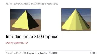
Projection Overview - 1 • Once the object has been transformed and it lies in the viewing frustrum we have to decide how to project the image onto screen • Selecting the location of the viewing plane inside the viewing frustrum can make things either easier or harder farther down the viewing plane
Projection Overview - 2 Perspective projection View Plane Parallel projection
Projection Overview - 3 • Parallel • If viewing down z-axis, just discard z component • Perspective • If viewing down z-axis, scale points based on distance. • x_screen = x / z • y_screen = y / z
Projection Overview - 4 • Usually not viewing down center of z axis. • Usually x = 0 and y = 0 at bottom left • Correct by adding 1/2 screen size • x_screen = x/z + 1/2 screen width • y_screen = y/z + 1/2 screen height • To get perspective right, need to know field of view, distance to screen, aspect ratio. • Often add scaling factor to get it to look right • x_screen = x*scale /z + 1/2 screen width
Perspective Transformation - 1 • Equations xper = d * x / z yper = d * y / z • Matrix Transformation Tper | 1 0 0 0 | [xc yc zc 1] * | 0 1 0 0 | = | 0 0 1 1/d | | 0 0 0 0 | = [xc yc zc (zc/d)]
Perspective Transformation - 2 • The viewing distance can be anything so consider using d= 1 to end up with normalized view plane coordinates • Matrix Transformation Tper1 | 1 0 0 0 | [xc yc zc 1] * | 0 1 0 0 | | 0 0 1 1 | | 0 0 0 0 |
Perspective Transformation - 3 • The viewing screen is not square you need to take the aspect ratio into account xper = d * x / z yper = d * y * ar / z d = (0.5) * width * tan(h / 2) • Matrix Transformation Tper1 | d 0 0 0 | [xc yc zc 1] * | 0 d*ar 0 0 | = | 0 0 1 1 | | 0 0 0 0 | = [(d*xc) (d*yc*ar)zc zc]
Clipping - 1 • This affects objects that are neither completely inside nor completely outside the viewing frustrum • Image Space Line Clipping • Use perspective projection to put all line on the screen • Clip lines during the rasterization phase of the 3D pipeline (so every object is processed for clipping even if it is completely inside viewing frustrum)
Clipping – 2 • Object Space Line Clipping • Use object space clipping to eliminate the objects that will not be visible before performing the perspective transformation • The idea is to use the perspective transformation to normalize the viewing frustrum by transforming it to a viewing cuboid that will make clipping perspective coordinates fairly easy
Screen Coordinates • Lighting and texture issues are ignored for the time being • Computing screen coordinates will depend on the kind of perspective transformation that was used • The aspect ratio will need to be taken into account for non-square screens
Screen Transformation - 1 • Equations d = 1 and FOV = 90 degrees xscreen = (xper + 1) * (0.5 * SCREEN_WIDTH - 0.5) yscreen = (SCREEN_HEIGHT – 1) – (yper+ 1) * (0.5 * SCREEN_HEIGHT - 0.5) • These equations can be simplified if = (0.5 * SCREEN_WIDTH - 0.5) = (0.5 * SCREEN_HEIGHT - 0.5) xscreen = + xper * yscreen = - yper *
Screen Transformation - 2 • Matrix Transformation Tscr1 | 0 0 0 | [xper yper 0 1] * | 0 - 0 0 | = | 0 0 1 0 | | 0 1 | = [(xper* + ) (-yper* + )0 1 ]
Screen Transformation - 3 • Equations for arbitary d and FOV xscreen = xper + (0.5 * SCREEN_WIDTH - 0.5) yscreen = -yper + (0.5 * SCREEN_HEIGHT - 0.5) • These equations can be simplified if = (0.5 * SCREEN_WIDTH - 0.5) = (0.5 * SCREEN_HEIGHT - 0.5) xscreen = xper + yscreen = -yper +
Screen Transformation - 4 • Matrix Transformation Tscr | 1 0 0 0 | [xper yper 0 1] * | 0 -1 0 0 | = | 0 0 1 0 | | 0 1 | = [(xper + ) (-yper + ) 0 1 ]
Screen Transformation - 5 • Equations for arbitary d and FOV xscreen = d*xcam/zcam + (0.5 * SCREEN_WIDTH - 0.5) yscreen = -d*ycam/zcam + (0.5 * SCREEN_HEIGHT - 0.5) • These equations can be simplified if = (0.5 * SCREEN_WIDTH - 0.5) • = (0.5 * SCREEN_HEIGHT - 0.5) d = (0.5) * viewplane_width * tan(h) xscreen = d*xc/zc + yscreen = -d*yc/zc +
Screen Transformation - 6 • Matrix Transformation Tcamscr | d 0 0 0 | [xc yc zc 1] * | 0 -d 0 0 | = | 1 1 | | 0 0 0 0 | = [(d*xc + zc*) (-d*yc + zc*) zc zc ]