Download
1 / 16
180 likes | 409 Vues
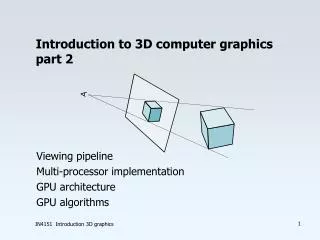
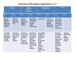
Introduction 3D Computer Graphics part 1. Projective display Viewing pipeline Graphics hardware Image-based rendering. z. y. x. x. d. n. o. Polygon models. n. v 8. Vertices defined with respect to world coordinate system with x,y,z coordinates. v 7. v 5. v 6. v 4. v 3. v 1.

E N D
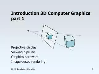
Introduction 3D Computer Graphicspart 1 Projective display Viewing pipeline Graphics hardware Image-based rendering IN4151 Introduction 3D graphics
z y x x d n o Polygon models n v8 Vertices defined with respect to world coordinate system with x,y,z coordinates v7 v5 v6 v4 v3 v1 v2 IN4151 Introduction 3D graphics
v t w Eye point Center of Projection u Center of Interest z y x Viewing transformation IN4151 Introduction 3D graphics
p z y p ’ q q ’ z COP d d x O x x' Perspective transformation IN4151 Introduction 3D graphics
Clipping • Clipping after perspective transformation • Take care of special cases (e.g. first remove points with negative z-coordinate) IN4151 Introduction 3D graphics
ywmax ywmin zwmax yvmax zwmin xwmax yvmin xwmin Window xvmax zdepthrange xvmin Viewport / screen Viewport transformation For standard case: IN4151 Introduction 3D graphics
dx/dy dx/dy dz/dx Rasterization • Set-up increments along the edges • Interpolate along edges and along spans • Interpolate shading, normals, texture coordinates over span IN4151 Introduction 3D graphics
framebuffer depthbuffer If (z < zdepthbuffer ) then setpixel Hidden-surface removal Wire frame Backface removal Hidden surface n view n Backface: IN4151 Introduction 3D graphics
Shading Light interaction with surface is complex: • reflects diffusely-specularly • is absorbed, and partly re-emitted, changes color • is transmitted, and at different position re-emitted • approximations are needed IN4151 Introduction 3D graphics
R f N f L V L Phong model Diffuse reflection reflects light equally into all directions Specular reflection reflects light around reflection direction Ambient term for indirect light IN4151 Introduction 3D graphics
0.0 0.1 0.3 0.5 0.7 3 6 9 25 200 0.25 0.2 0.0 0.4 0.5 0.75 0.6 0.8 1.0 Reflection parameters IN4151 Introduction 3D graphics
I 1 (x ,y ) 1 1 I I I a s b (x ,y ) ,y ) a s (x b s (x ,y ) s s I 4 (x ,y ) I 4 4 2 (x ,y ) 2 2 I 3 (x ,y ) 3 3 Gouraud shading To avoid faceted effect, calculate intensity at vertices and interpolate over facet normal at vertices are interpolated from normals of adjacent polygons faceted appearance smooth appearance IN4151 Introduction 3D graphics
v y pixel u x texture object screen texture screen Texture mapping • Texture mapping is a composed 2D perspective transformation • Perspective projection maps “pre-image” in texture space to image space • Filtering is required IN4151 Introduction 3D graphics
u d R R G B R v G B B G Mipmap Mipmap is image pyramid with increasingly filtered/compressed images polygon in perspective projection rasterized and textured texture map IN4151 Introduction 3D graphics
= + a d ~ Anti-aliasing Point sampling Area sampling Alpha blending / compositing Special cases IN4151 Introduction 3D graphics