Introduction to 3D Graphics
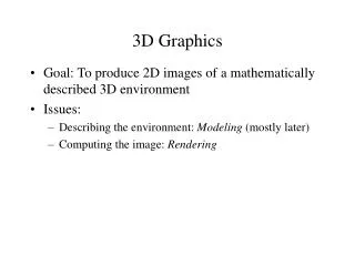
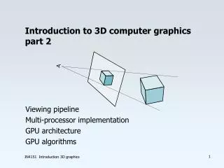
Introduction to 3D Graphics. Using OpenGL 3D. Classical Polygon Graphics (H/W) Pipeline. Mesh objects with 3D polygons (triangles or quads usually) Apply material properties to each object Texture-map polygons as needed Light scene Place camera Render each polygon Enjoy the view.

Introduction to 3D Graphics
E N D
Presentation Transcript
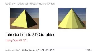
Introduction to 3D Graphics Using OpenGL 3D 3D Graphics using OpenGL – 9/11/2014
Classical Polygon Graphics (H/W) Pipeline • Mesh objects with 3D polygons (triangles or quads usually) • Apply material properties to each object • Texture-map polygons as needed • Light scene • Place camera • Render each polygon • Enjoy the view 3D Graphics using OpenGL – 9/11/2014
Why OpenGL for 3D? • Widely used in industry and academia for interactive or real-time 3D graphics • Old fixed-function API (OpenGL 1.x) assisted rapid prototyping of simple 3D scenes with “classical” lighting effects • Experiment with simple ideas quickly • Modern programmable API allows for more flexibility and control • TAs will provide shaders to replace the fixed-function API functionality for projects/labs; you will write your own in Phong lab 3D Graphics using OpenGL – 9/11/2014
3D Polygons (1/2) • Material specification • Describes the light reflecting properties of the polygon • Color, shininess, reflectiveness, etc. • Provided as input to shader • Provide values as uniforms to apply to entire shapes • Provide values as attributes to apply to individual vertices // Pale yellow, opaque (alpha defaults to 1 in our shader) glUniform3f(glGetUniformLocation(shaderID, “color”), 1.0, 1.0, 0.3 }; 3D Graphics using OpenGL – 9/11/2014
3D Polygons (2/2) • OpenGL defaults to a right-handed coordinate system • 3D polygons are defined like 2D polygons: GLfloatvertexData[] = { 0, 75, 0, // Vertex 1 50, 0, 50, // Vertex 2 50, 0, 50, // Vertex 3 }; • This defines one triangle • Coordinate values are arbitrary - can set virtual camera up to capture any size scene, so use convenient values • Remember counter-clockwise winding order! 3D Graphics using OpenGL – 9/11/2014
Complexities of Light Reflection from Surfaces – Need to Know Intensity and direction of all light that strikes a point on object's surface, whether directly from light source or after many bounces from other objects ( global illumination) How an object's surface appears to us as it reflects, absorbs, and diffracts light (“material properties”) Location of eye/camera relative to scene Distribution of intensity per wavelength of incident light Human visual system (HVS) and itsdifferential, highly non-linear response to light stimuli Lights may have geometry themselves Standard lighting/illumination models address these complexities (except for HVS) 3D Graphics using OpenGL – 9/11/2014
An Imperfect World – Model via Approximations • Classic lighting models (also called illumination or reflection models, not to be confused with shading models discussed later) developed at the dawn of raster graphics in early 70s. • Epicenter at University of Utah where Ivan Sutherland worked with David Evans • Spawned the Evans & Sutherland flight simulator (with graphics) business • Other pioneers: • Henri Gouraud (shading model – filling in interior pixels from colors at vertices of a triangle) • Bui TuongPhong (lighting and shading models) • Martin Newell (the Utah teapot (SIGGRAPH icon), meshing algorithms) • James Clark (geometry engine, Silicon Graphics, Netscape) • John Warnock (Hidden Surface Elimination, Adobe) • Ed Catmull (splines, Pixar, Disney) • Alvy Ray Smith (SuperPaint, HSV color space, partnered with Catmull on LucasFilm -> Pixar) • etc... 3D Graphics using OpenGL – 9/11/2014
An Imperfect World • Back then: • CPUs > 4 orders of magnitude less powerful, no GPU to speak of, just plot pixels • memory limited (measured in KB!) • Even on today's machines, a physically accurate light simulation requires computational power beyond the capabilities of supercomputers! 3D Graphics using OpenGL – 9/11/2014
Lighting (Illumination) Models (1/2) • Idir = measure of intensity of directional light (all rays parallel) at point of contact with surface • θ = angle between surface normal (n) and vector from light source ( ) Facing light source: Maximum reflection • Note: Idirand all the other quantities in the lighting model are fractions between 0 and 1. • These units are convenient BUT completely arbitrary and not physically based! to light source: No reflection In between: Some fraction of light reflected • Color of point on surface dependent on scene lighting and surface material • First approximation: model diffuse reflection from a matte surface (light reflected equally in all directions, viewer-independent) based only on angle of surface normal to light source • Modeling light "drop-off“ with angle to light • Lambert's diffuse-reflection cosine law • for reflected light intensity I 3D Graphics using OpenGL – 9/11/2014
Lighting (Illumination) Models (2/2) • Lambert light attenuation based on surface's angle to light source • Visualization of Lambert's law in 2D • Note: we will crudely approximate the intrinsic material properties of the object with RGB values. For example, the greater the R, the more reddish the object will appear under white light. • In reality, need surface texture and wavelength-dependence 3D Graphics using OpenGL – 9/11/2014
Shading Rule (1/6) www.sklardevelopment.com/graftext/wpf/3d • Goal: finding color at each pixel, preferably w/o having to evaluate a full lighting model at each pixel • First approach: Lambert's cosine law (flat/constant shading for whole facet) • faceted appearance, perfect for this rectangular pyramid. • What if we want to approximate a rounded object? • Lambert-shaded, faceted; appearance is no longer ideal 3D Graphics using OpenGL – 9/11/2014
Shading Rule (2/6) • First solution: increase the number of polygons • Better shape approximation, more expensive to render • Ultimately, still faceted when rendered (higher poly count => less faceted) • Adaptive meshing is an improvement - more polygons in areas of high curvature “Utah Teapot” by Martin Newell 3D Graphics using OpenGL – 9/11/2014
Shading Rule (3/6) • Get this: • Want this: faceted shading smooth shading 3D Graphics using OpenGL – 9/11/2014
Shading Rule (4/6) The normal at a vertex is the same as the plane normal. Therefore, each vertex has as many normals as the number of planes it helps define. Only one vertex normal per vertex; average of face normals of the faces the vertex is part of • Gouraud smooth shading • compute lighting equation at each vertex of mesh • linearly interpolate vertex color values to get colors at all points • weighted averaging: the closer the point is to a vertex, the more it is influenced by that vertex • How do we determine vertex colors? Need a normal… • Vertex normals are an artifice; the normal is mathematically undefined since a vertex is a discontinuity • we hack around this by averaging 3D Graphics using OpenGL – 9/11/2014 Faceted Smooth
Shading Rule (5/6) 2D curve approximation (vertex normals in green) Vertex normals shown in color, face normals in black mesh approximation • Vertex normals • if vertex used by only one face, normal is set to face's normal • typically computed from the plane equation • otherwise, normal is set to average of normals of all faces sharing it • if mesh is not too coarse, vertex normal is a decent approximation to the normal of modeled surface closest to that vertex • adaptive meshing adds more triangles in areas with rapid changes in curvature 3D Graphics using OpenGL – 9/11/2014
Shading Rule (6/6) • Programmable OpenGL API doesn’t provide any lighting or shading. Use shaders to implement lighting and shading model of your choice (We give you these for now). • to get flat shading, specify the same surface normal for vertices of the same facet (each vertex gets nnormals, where n is the number of facets it is a part of) • to get smooth shading, you must specify a single shared normal for each (shared) vertex in the object 3D Graphics using OpenGL – 9/11/2014 Faceted Smooth
Interpolation vs Flat Shading Summary 3D Graphics using OpenGL – 9/11/2014
Vertex Normals (1/2) • Sending vertex normal to the shader requires a small extension to the way we specify vertices • Each vertex is now a position plus a normal, e.g., GLfloat[] vertexData = { -1, 0, 0, // Position 1 0, 0, -1, // Normal 1 1, 0, 0, // Position 2 1, 0, 0, // Normal 2 … }; • Normals needn’t be axis-aligned, of course… • For flat shading a shared vertex has as many (position, normal) entries as the facets it’s a part of 3D Graphics using OpenGL – 9/11/2014
Vertex Normals (2/2) • Enable the normal attribute glEnableVertexAttribArray(<normal identifier>); • Make two calls to glVertexAttribPointerinstead of one (like in 2D), one for positions and one for normals. We must adjust some parameters: • size parameter is now 3 since we have 3 elements per vector • stride specifies how far apart values of the same type (position/normal) are in our array (in bytes). Here stride is 6*sizeof(GLfloat) for both position and normal (the first element of each position/normal is 6 floats away from the next position/normal). • pointer is still (void*)0 for position, and is (void*)(3*sizeof(GLfloat)) for normals. First position starts 0 bytes into the array, first normal starts 3 floats into the array (use sizeof(GLfloat) to get bytes in a float) . • glDrawArrays(GL_TRIANGLES, 0, <number of tri’s>) replaces our 2D draw call. Now we’re drawing triangles instead of quads. Remember to bind the VAO before drawing and unbind it after. 3D Graphics using OpenGL – 9/11/2014
VBOs and VAOs • VBO is a byte array, we’re only going to use GL_FLOAT when using the VBO, so we can think of it as a float array. Remember to use sizeof(GLfloat) when byte values are needed. • VAO holds our representation of the data 0 1 2 3 4 5 6 7 8 9 10 11 12 13 14 15 16 … 17 Triangle 1 size (3) 0 1 2 3 4 5 6 7 8 9 10 11 12 13 14 15 16 … Position 1 Normal 1 Position 2 Normal 2 Position 3 Normal 3 17 Normal Pointer: (void *)(3*sizeof(GLfloat)) Position Pointer: (void *)0 Stride: (void *)(6*sizeof(GLfloat)) 3D Graphics using OpenGL – 9/11/2014
Reflectance (Illumination, Lighting) Model (1/8) • Non-geometric lights: • Ambient: crude approximation to inter-object (“global”) reflection, all surfaces receive same light intensity. Allows all facets to be minimally visible • Directional: illuminates all objects equally from a given direction; light rays are parallel (models sun, sufficiently far away) • Geometric lights: • Point: Originates from single point, spreads outward equally in all directions • Spotlight: Originates from single point, spreads outward inside cone’s directions 3D Graphics using OpenGL – 9/11/2014 Spotlight Directional Point
Reflectance Model (2/8) // ambient term is specified as RGB(A). Use glUniform4f to provide optional alpha value glUniform3f(<Ambient Identifier>, 0.2, 0.2, 0.2); // vectors are XYZW quadruple, w = homogeneous coordinate (see Transformations lecture) // if no need for homogenous coordinate, use glUniform3f instead glUniform3f(<Position Identifier>, 10.0, 5.0, 8.0); glUniform3f(<Direction Identifier>, 1.0, 2.0, 3.0 ); // If our shader supports multiple types of lights, specify an integer constant to describe // type of light glUniform1i(<Type Identifier>, POINT_LIGHT_TYPE); // To use a directional light glUniform1i(<Type Identifier>, DIRECTIONAL_LIGHT_TYPE); 3D Graphics using OpenGL – 9/11/2014
Reflectance Model (3/8) • Many models exist to approximate lighting physics – more accurate, more computation • Fixed-function OpenGL: Phong reflection model, survives today (though crude) • Implemented in fixed function hardware for decades, easily implemented in shaders • approximates lighting by breaking down into three components: ambient, diffuse, specular • can think of these as coincident, independent layers, each with its own characteristics, and sum them to get the final result • non-global illumination model – model does not handle inter-object reflections 3D Graphics using OpenGL – 9/11/2014
Reflectance Model (4/8) • Equation is wavelength-dependent; approximate with separate equations for • All values unitless real numbers between 0 and 1 • Evaluates total reflected light I at a single point, based on all lights Ambient Component Diffuse Component Specular Component 3D Graphics using OpenGL – 9/11/2014
Reflectance Model (5/8) • Variables • = wavelength / color component (e.g. R, G, and B) • = total amount of light reflected at the point • = intensity of light incident at a specific point on surface • = intensity of ambient light used in scene; similar for diffuse, specular • = innate color of object's material at specific point on surface (RGB approximation) • = object’s efficiency at reflecting light • Since both and are dimensionless fractions we really only need one of them • Ambientcomponent • -- think of as the fraction of reflected for that . Note that we use for the ambient component • effect on surface is constant regardless of orientation, no geometric information • total hack (crudest possible approximation to global lighting based on inter-object reflection), but makes all objects a little visible - scene looks too stark without it 3D Graphics using OpenGL – 9/11/2014
Reflectance Model (6/8) • Diffuse component (R component shown below, same for G, B) - viewer independent! • uses Lambert's diffuse-reflection cosine law • = light’s diffuse color • = the efficiency of incident light reflection • = innate color of object's diffuse material property at specific point on surface • = Lambert's attenuation factor where is the angle between normal and light vector 3D Graphics using OpenGL – 9/11/2014
Reflectance Model (7/8) • Specular Component (for R) – viewer-dependent • highlights seen on shiny objects (plastic, metal, mirrors, etc.) • cosine-based attenuation factor ensures highlight only visible if reflected light vector and vector to viewer are closely aligned • n = specular power, how "sharp" highlight is – the sharper, the more intense • specular highlight of most metals are the color of the metal but those on plastic, shiny apple, pearl, etc. are mostly the color of the light (see Materials chapter 27) e = viewpoint r = reflected image of light source ℓ = vector from the light source n = surface normal δ= angle between eand r n = specular coefficient Note: Fixed-function OpenGL uses a slightly different lighting model called Blinn-Phong. See 14.9.3 3D Graphics using OpenGL – 9/11/2014 Specular falloff of cosn
Reflectance Model (8/8) • Attenuation factor • Used in diffuse and specular light calculation: • Directional lights have no attenuation (infinitely far away) • Geometric lights (point lights, spot lights) get dimmer with distance • Inverse square law • Area covered increases by square of distance from light • Thus, light intensity is inversely proportional to the square of the distance from light • A light twice as far away will be one quarter as intense • Though the physics say inverse square law, it doesn't always look good in practice so OpenGL lets you choose the attenuation function (quadratic, linear, or constant) ...... d d d 3D Graphics using OpenGL – 9/11/2014
Texture Mapping (1/2) • Goal: adding more detail to geometry of scene without adding complexity • Solution: texture mapping • used extensively in video games, e.g., for backgrounds, billboards • also used for many other techniques such as level-of-detail management • cover the mesh's surface in stretchable "contact paper" with pattern or image on it • in general, difficult to specify mapping from contact paper to every point on an arbitrary 3D surface • mapping to planar polygons is easy: specify mapping for each vertex and interpolate to find mapping of interior points 3D Graphics using OpenGL – 9/11/2014
Texture Mapping (2/2) • Specifying "texture point" mapped to particular vertex • requires coordinate system for referring to positions within texture pixmap • convention: • points on pixmap described in abstract floating-point "texture-coordinate system" • axes labeled u and v, range 0 to 1. • origin located at the upper-left corner of the pixmap 3D Graphics using OpenGL – 9/11/2014 (0,0) U axis (1,0) V axis (0,1)
Texture Mapping UV Coordinates • Let’s map from two coplanar triangles from a face in the 3D model to a texture map • Texture map uses UV texture coordinates: just use ratios • Texture mapping arbitrary solids is much harder – we’ll study this later 3D Graphics using OpenGL – 9/11/2014
Texture Mapping Example (1/2) • We add texture coordinates in the same way we added normals. For clarity we’ll leave out normals from this example. • First add the texture coordinate for each vertex to our data array GLfloat[] vertexData = { -10, 0, 0, // Position 1 0, 1, 0, // Normal 1 0, 0, // Texture Coordinate 1 10, 0, 0, // Position 2 0, 1, 0, // Normal 2 1, 0, // Texture Coordinate 2 … }; 3D Graphics using OpenGL – 9/11/2014
Texture Mapping Example (2/2) • Enable the texture coordinate attribute glEnableVertexAttribArray(<texcoord location>); • Define texture coordinates like normals, except the glVertexAttribPointer parameters are slightly different. • size parameter is still 3 for positions and normals, now 2 for texture coords • strideis now 8*sizeof(GLfloat) for position, normal, and texture coordinate (because we have 8 floats per vertex instead of 6). • pointer is still (void*)0 for position, (void*)(3*sizeof(GLfloat)) for normal and (void*)(6*sizeof(GLfloat)) for texture coordinates (remember these values are in bytes). 3D Graphics using OpenGL – 9/11/2014
Texture Mapping (Tiling) • Create a brick wall by applying brick texture to plane • Produces realistic-looking image, but very few bricks in wall • Tiling increases number of apparent bricks 3D Graphics using OpenGL – 9/11/2014
Texture Mapping (Stretching) • Create a sky backdrop by applying a sky image to a plane • Would look unnatural if tiled • Stretch to cover whole plane • Your texture shader can implement tiling and stretching by multiplying UV coordinates by a value >1 for tiling and <1 for stretching 3D Graphics using OpenGL – 9/11/2014
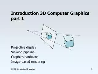
Camera (1/3) • Camera Properties: • Perspectiveor Orthographic • Position: placement of camera • Look Direction: direction camera is aimed (vector determining lens axis) • Up Direction: rotates camera about look vector, specifying which way is “up” – must not be collinear to the look vector • Far-Plane Distance: objects behind do not appear • Near-Plane Distance: objects in front do not appear • Field Of View: (Height Angle) • Aspect Ratio (Relative width and height) 3D Graphics using OpenGL – 9/11/2014
Camera (2/3) Center of Scene (used to compute LookAtDirection) • Perspective Projection Projection ofUp Direction Up Direction FOV in y-direction Position y Near-Plane Distance Far-Plane Distance 3D Graphics using OpenGL – 9/11/2014
Width Far distance Height Center of scene Near distance Projection of up vector Up vector Position Camera (3/3) • Orthographic Projection 3D Graphics using OpenGL – 9/11/2014
OpenGL Camera • Fixed-function API has support for perspective and orthographic cameras • With the Programmable API you must construct and supply all model, view, and projection matrices, and then use them in your shaders • In the Viewing lectures you will learn how to construct these matrices yourselves and you will construct them in the Camtrans lab (We will take care of the camera until then) • In the shader labs you will learn how the matrices are used in the shader 3D Graphics using OpenGL – 9/11/2014
WPF3D Lablets (1/2) • Hands on exploration of concepts discussed in this lecture • Modeling smooth surfaces www.sklardevelopment.com/graftext/wpf/3d 3D Graphics using OpenGL – 9/11/2014
WPF3D Lablets (2/2) • Lighting and shading model www.sklardevelopment.com/graftext/wpf/3d 3D Graphics using OpenGL – 9/11/2014
Book Sections • Intro • Chapter 6 3D Graphics using OpenGL – 9/11/2014