Download
1 / 12
150 likes | 608 Vues
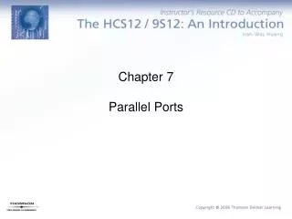
I/O PORTS. Module Objectives. Configure any pin as either input or output Read or write data from/to port pin Understand which pins have alternate functions Module exercise: Configure an I/O port to have 4 inputs and 4 outputs. Then based on the state of the inputs change the state of

E N D
Module Objectives • Configure any pin as either input or output • Read or write data from/to port pin • Understand which pins have alternate functions • Module exercise: Configure an I/O port to have 4 inputs and 4 outputs. Then based on the state of the inputs change the state of the outputs.
V DDA PORT BLOCK DIAGRAM INTERNAL BUS M68HC08 CPU PTA7 – PTA0 CPU ARITHMETIC/LOGIC REGISTERS UNIT (ALU) DIRECT MEMORY ACCESS MODULE PTB7 – PTB0 CONTROL AND STATUS REGISTERS — 88 BYTES BREAK MODULE USER EPROM — 36,864 BYTES PTC7 – PTC0 LOW-VOLTAGE INHIBIT MODULE USER RAM — 1024 BYTES PTD7/KBD7 – PTD0/KBD0 COMPUTER OPERATING PROPERLY MODULE MONITOR ROM — 240 BYTES PTE7/TCH3 PTE6/TCH2 USER EPROM VECTOR SPACE — 32 BYTES TIMER INTERFACE PTE5/TCH1 MODULE PTE4/TCH0 OSC1 PTE3/TCLK CLOCK GENERATOR OSC2 PTE2/TxD MODULE SERIAL COMMUNICATIONS INTERFACE CGMXFC PTE1/RxD MODULE PTE0 PTF5 SYSTEM INTEGRATION RST PTF4 MODULE PTF3/MISO PTF2/MOSI SERIAL PERIPHERAL INTERFACE IRQ1 /V MODULE IRQ PTF1/SPSCK PP MODULE IRQ2 PTF0/ SS POWER-ON RESET PTG3 – PTG0 MODULE (64-PIN PACKAGE ONLY) V SS V DD POWER PTH3 – PTH0 (64-PIN PACKAGE ONLY) CGND/EVss
I/O Port Pins • Up to 54 bidirectional input/output pins • On 8 different I/O ports: A, B, C, D, E, F, G, and H PortA - 8 pins PortB - 8 pins PortC - 8 pins PortD - 8 pins PortE - 8 pins PortF - 6 pins PortG - 4 pins ( on 64 pin QFP packages only ) PortH - 4 pins ( on 64 pin QFP packages only ) • All functionally identical
INTERNAL DATA BUS Read Data Direction Register Write Data Direction Reg. • • DDRXn RESET • • PTXn Write Port Register PTXn • Read Port Register • Single I/O Pin Block Diagram
READ: DDRx DDRx7 DDRx6 DDRx5 DDRx4 DDRx3 DDRx2 DDRx1 DDRx0 WRITE: RESET: 0 0 0 0 0 0 0 0x = A, B, C, D, E, F, G, or H Note: Ports F, G and H do not support all 8 bits. See reference manual. Configuring Port Pins • Data Direction Registers (DDRx) • Determines direction, input or output, of each port pin 1 = Corresponding port pin configured as output 0 = Corresponding port pin configured as input • All pins are configured as inputs upon reset
READ: PTx PTx7 PTx6 PTx5 PTx4 PTx3 PTx2 PTx1 PTx0 WRITE: RESET: UNAFFECTED BY RESET x = A, B, C, D, E, F, G, or H Note: Ports F, G and H do not support all 8 bits. See reference manual. Reading and Writing Data • Port Data Register • Pin Configured as Input Read - Reads voltage level on pin Write - Latches new value, but does not affect pin • Pin Configured as Output Read - Reads last latched value Write - Changes output to that level • To avoid data glitches port data register should be written before any pins are configured as outputs in data direction register
Shared Pins • Some pins share functions with other system modules • PortD pins shared with XIRQ module (XL36) • All pins • Individual enable/disabled • PortE pins shared with TIM and SCI modules (XL36) • TIM uses PTE7-PTE3 • SCI uses PTE2, PTE1 • PortF pins shared with SPI module (XL36) • SPI uses PTF3 - PTF0 • When not being used by submodule, can be used as I/O
Module Exercise: Parallel I/O Routine • Write a routine that configures port C bits 7, 5, 3, & 1 as inputs and bits 6, 4, 2, & 0 as outputs. The output pins should be initialize to low(0) levels. The routine must read the input pins and then set the next lowest pin to that input. • Example: • If PTC7 is high(1), set PTC6 • If PTC7 is low(0), clear PTC6 etc. • Write your program here: Suggested program steps: • DDRC EQU $6 Address of Data Direction Register C • PORTC EQU $2 Address of Data Register C • ORG $6E00 Originate program at address $6E00 • 1. Load A with output value. • 2. Store A to Data Register C. • 3. Load A with value to define inputs and outputs. • 4. Store A to Data Direction Register C. • 5. Read Inputs, load A from port C. • 6. Shift bits to right • 7. Change outputs • DONE BRA DONE 8. Done, stay here. HC08-P I/O Exercise
Port A Data Register (PTA) Port B Data Register (PTB) Port C Data Register (PTC) Port D Data Register (PTD) Port A Data Direction Register (DDRA) Port B Data Direction Register (DDRB) Port C Data Direction Register (DDRC) Port D Data Direction Register (DDRD) Port E Data Register (PTE) PTF5 PTF4 PTF3 PTF2 PTF1 PTF0 PTG3 PTG2 PTG1 PTG0 PTH3 PTH2 PTH1 PTH0 Port E Data Direction Register (DDRE) DDRF5 DDRF4 DDRF3 DDRF2 DDRF1 DDRF0 DDRG3 DDRG2 DDRG1 DDRG0 DDRH3 DDRH2 DDRH1 DDRH0 REGISTER SUMMARY 68HC08XL36 - 64 Pin Package
Module Exercise Solution: Parallel I/O Routine • Write a routine that configures port C bits 7, 5, 3, & 1 as inputs and bits 6, 4, 2, & 0 as outputs. The output pins should be initialize to low(0) levels. The routine must read the input pins and then set the next lowest pin to that input. • Example: • If PTC7 is high(1), set PTC6 • If PTC7 is low(0), clear PTC6 etc. • Write your program here: Suggested program steps: • DDRC EQU $6 Address of Data Direction Register C • PORTC EQU $2 Address of Data Register C • ORG $6E00 Originate program at address $6E00 • LDA #$00 1. Load A with output value. • STA PORTC 2. Store A to Data Register C. • LDA #$55 3. Load A with value to define inputs and outputs. • STA DDRC 4. Store A to Data Direction Register C. • LDA PORTC 5. Read Inputs, load A from port C. • LSRA 6. Shift bits to right • STA PORTC 7. Change outputs • DONE BRA DONE 8. Done, stay here. HC08-P I/O Exercise