Download
1 / 31
310 likes | 328 Vues
This article discusses the commissioning experience of the Injector/Linac at LCLS, including beam parameters, layout, tuning techniques, emittance measurements, simulations, control system applications, and ongoing tasks.

E N D
Injector/Linac Commissioning Experience C. Limborg-Deprey , for the LCLS Commissioning TeamDOE Status Meeting for the LCLSJuly 11, 2007
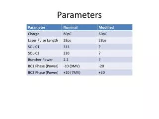
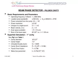
Beam Parameters • Q 0.2-0.5 nC • fRF= 30 Hz • Egun 110 MV/m • gex,y 1.2 mm (at 135 MeV ) • gex,yslice 1.0 mm , • DtFW 6.5 ps • Ipk 30-75 A • Egun 5.8 MeV • QE 5×10⁻⁶ (or more recently closer to 10-5)
LCLS Injector/Linac Layout 6 MeV OTR screens (7) YAG screens (7) RF Gun Wire scanners (7) Gun Solenoid Dipole magnets (8) Beam stoppers (2) S-band RF acc. sections (5) L0a Gun Spectrometer L0b Emittance Screens/Wires Emittance Screen/Wires RF Deflector L1S 2-km point in 3-km SLAC linac X-band RF acc. section BC1 135-MeV Spectrometer TD11 stopper 135 MeV 250 MeV
BC1 Gui • Gui for adjusting compression • Moves chicane • Set magnets for R56 • Corrects dispersion • Set Linac phases for phasing to rest of linac
Orbit Steering Gui for Orbit Steering Region of interest Correctors of interest SVD method Minimize rms orbit w.r.t gold with minimum correctors strength Developed by E.Prat ,DESY
Emittance measurements • Tuning • Laser Alignment, Phase scans, orbit correction • Minimizing beam size with solenoid • Matching • Choice of method • Injector( 3-screen, Quad-Scan, 3 Wire-Scanners) • BC1 (Quad-Scan, 3 Wire-Scanners) • Slice emittance • (H) combination with TCAV • (V) in dispersive region
Laser Alignment • with respect to solenoid • (very good alignment solenoid w.r.t gun) • minimize variation of position with solenoid scan
Tuning L0a Laser L0b L1S RF Phases
Tuning Energy spread minimization at gun exit Measure energy spread in gun spectrometer Emin = 19keV(rms) Calibration: 8.8eV/micron Laser Phase
Matching Matching GUI 135 MeV , after BC1 Loads current beam parameters (magnets ,RF , twiss parameters) Optimize quad settings for matching to given (,) Apply them
Emittances at 470pC (July 3rd ) ex = 1.22 mm-mrad x= 1.03 ey = 1.18 mm-mrad y= 1.00
Emittance Studies with Bucking Coil Bbuck = -0.087 Bbuck = -0.027 Bbuck = 0.087 200pC, Jun 30th -07
Slice Emittance Measurements With good laser pulse shaping Temporal shape (7.1 ps FWHM) 400pC, June 29th -07
Slice Emittance Measurements 3rd July ~ 500 pC
Emittance scan – July 3rd Simulations Oct-06 (PARMELA) 0.5 nC , 100 MV/m , r = 0.8 mm Measurements 0.4 nC , 110 MV/m , r = 0.7 mm -2% +2%
Measurement of Intrinsic Emittance At 30 pC ,May 19th At 30 pC , June 5th 30pC, July 3rd , after “cleaning” not perfectly optimized yet
Emittance degradation at high charge • L1X degrades horizontal emittance • BC1 degrades both (without compression) Wakefields in L1X Coupler in L1X Wakefields in BC1?
S2E simulations • Start-to-end simulations effort : • Parallel codes : IMPACT and ASTRA PARMELA being parallelized too (Elegant, Ginger/Genesis downstream) • Interface user-friendly developed by control system • directly reads machine parameters through EPICS (“live” mode) • generate distribution from laser profile measured (not linked yet) • Issue : poor access to intensive computer power
Comparison With Simulations From Jun20th -07 Parameters changed since then (in particular cathode surface evolved)
Control System applications • LLRF feedback systems running well • temporary feedback systems allowed stable operation • Alarms now on • Some physics app. migrated to permanent • Bunch length measurement • Profile monitor
Charge Stability Charge stability July 6th -07 ~ 3.9 %
To-Do-list • Phase Cavity commissioning • Commissioning OTRS1 • Uncorrelated energy spread • Weekly monitoring of cathode health (imaging + thermal emittance) • More Emittance Minimization needed
More Emittance minimization needed • Parametrization • vs Injection Phase • vs longitudinal laser (shape, length) • vs L0a gradient • vs laser radius • … • for different charges • Degradation with CSR
Summary • Late start but fast start • More of control system /diagnostics were ready • QE lower (a factor ~3) than expected but 500pC over the past week • Good emittances at 200-500pC • Beam seems to meet required quality at end injector • Emittance preservation under study • Identification of some issues in L1X / BC1 • Start-to-End simulation wrapper built • but more CPU needed
Laser Spatial and Temporal Shaping R = 0.7 mm Temporal shape (7.1 ps FWHM) Spatial shape on cathode using iris
Jitter at 500 pC (10 Hz, 10 sec) 0.45% RMS Energy Jitter @ BC1 (L1S j = 25º, L1X j = -20º) 0.05% RMS Energy Jitter @ DL1 4.9% RMS Charge Jitter (10 sec)
Hor. emittance growth in X-band RF L1S X-band RF acc. section BC1 stopper gex Dx = 1.2 mm gey ~65 μrad pk (1.3 keV) X-band RF ON X-band RF OFF x kick at downstream BPM
Transverse Wakefield in X-Band Structure Q 500 pC BC1 OFF X-band RF OFF gex(μm) Dx = +0.6 mm
100MV/m, 2 Gaussians, 0.5 nC < {10,90} > ~ 0.7 mm-mrad Parameters improved by using a 0.6 mm radius beam 80 ~ 0.78 mm-mrad < {10,90} > ~ 0.6 mm-mrad