Advanced Techniques for Synchronous Motor Drives
310 likes | 501 Vues
Explore open-loop volts/Hz speed control, self-control, separate control & features of synchronous motors with square wave or PWM inverters. Learn about brushless excitation & commutation principles for efficient motor operation.

Advanced Techniques for Synchronous Motor Drives
E N D
Presentation Transcript
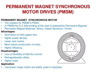
Contents • Open loop volts/HZ speed control of synchronous motors. • Self control. • Separate control. • Attractive feature of a synchronous motor. • Synchronous motor operating with square wave inverter • Synchronous motor operating with pwm inverter • Brushless excitation of synchronous machine
Open loop volts/Hz speed control of synchronous motors.(Control of Synchronous Motors) • Possible with variable frequency converter. • Variable frequency synchronous motor can be controlled to possesses the characteristics of a separately excited dc motor. (E & V are controlled in proportion to frequency in order to keep air gap flux constant)
Self control A Synchronous motor in self controlled mode is called “commutator less Dc motor”. The frequency becomes the slave the speed.
Basic features of self-controlled synchronous machine • The inverter, controller and absolute position encoder - act as electronic commutator • Electronic commutator replaces the mechanical commutators and brushes (mechanical inverter) of traditional dc machine • The flux phasor diagram rotate at synchronous speed
Basic features of self-controlled synchronous machine Control can modify the angle between the flux phasors Because of self-control, machine does not show any stability or hunting problem of traditional synchronous machine The transient response is fast – similar to dc machine The rotor inertia is smaller than dc machine with high energy magnet 8
Self Control Principle • Commutation of the converter feeding the motor is controlled through the rotor position information from a shaft encoder. • Under over excitation the motor voltages can be employed to commutate the thyristors at the inverter. Now the inverter becomes simple. But at low speeds commutation assistance is required.
Rotor position is sensed and the firing signals to the devices are synchronized to the motor position. • For every 600 rotation of the rotor a new device in the sequence is fired. Contd..
For rotation of the rotor by 2 pole pitches all the six devices will receive firing pulses. • Using this control the angle between the rotor and the stator mmf (Torque Angle) can be controlled. This is not possible in separately excited motor. • Synchronous motor in self control is called as Commutator less motor having the steady state performance of the separately excited DC motor
Separate control The speed is the slave the frequency.
Separate control principle • Supply Frequency to the synchronous motor is controlled from the inverter which receives its firing pulses from a frequency controlled oscillator. • The machine will exhibits conventional behavior. • Up to base speed the motor operates at constant torque and above base speed are obtained by clamping the voltage at rated voltage. Frequency can be increased and the motor operates in flux weakening region
Draw backs of Separate control • Hunting • Poor dynamic Behavior.
Attractive feature of a synchronous machine • Load commutation is possible only with CSI and not with VSI. Load Commutated Inverter fed Synchronous Motor
When forced commutation is required, the motor may be operated at UPF. • To provide the necessary reactive power of the converter when the motor is over excited • Load Commutation can be used when the cycloconverter is feeding the motor. When using cycloconverter, commutation difficulty is over come by utilising line commutation.
Synchronous motor operating with square wave inverter • Speed Range • Medium to High • Braking • Dynamic Braking Possible. Regeneration not straight forward. • Harmonics • Heating effect is high at lower frequency Contd..
Torque Pulsations • Problem at Low speed • Power Factor • Low Line pf • High Cost • Efficiency • Moderately good • Open loop Control is possible. • Staring by cage winding or by open loop method Contd..
Features • Speed Range • Very wide Speed range upto zero speed is possible • Braking • Dynamic Braking Possible. Regeneration possible if primary supply is dc. • Harmonics • Nearly Sinusoidal
Torque Pulsations • Minimal • Power Factor • Line pf closer to Unity. • High Cost • Efficiency • Good • Open loop Control is possible.
References • Bimal K. Bose. ‘Modern Power Electronics and AC Drives’, Pearson Education, 2002. • G.K. Dubey, ‘Power semi-conductor controlled drives’, prentice hall of india, 1989.