Download

1 / 45

E N D
Stability of columns
Columns and sturts: Structural members subjected to compression and which are relatively long compared to their lateral dimensions are called columns or Struts. Generally, the term column is used to denote vertical members and the term strut denotes inclined members Examples: strut in a truss, Piston rods, side links in forging machines, connecting rods etc.
Stable, Neutral and unstable Equilibrium Stable equilibrium: A stable equilibrium is one in which a body in static equilibrium on being displaced slightly, returns to its original position and continues to remain in equilibrium.
Neutral equilibrium: A neutral equilibrium is one in which a body in equilibrium, on being displaced does not returns to its original position, but its motion stops and resumes its equilibrium state in its new position.
Unstable equilibrium: An unstable equilibrium is one in which a body in equilibrium on being slightly disturbed, moves away from its equilibrium position and loses its state of equilibrium.
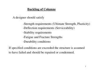
Buckling Load: The maximum load which a column can support before becoming unstable is known as buckling load or crippling load or critical load At this stage, the maximum stress in the column will be less than the yield stress (crushing stress) of the material. The buckling takes place about the axis having minimum radius of gyration or least moment of inertia.
Safe load: It is the load to which a column is subjected to and is well below the buckling load. It is obtained by dividing the buckling load by a suitable factor of safety. safe load = buckling load / factor of safety Stability factor: The ratio of critical load to the allowable load on a column is called stability Factor
P P MODES OF FAILURE OF THE COLUMNS The mode of failure of columns depends upon their lengths and depending on the mode of failure columns are classified as a. Short columns b. Long columns Short Columns: A short column buckles under compression as shown in figure and fails by crushing. The load causing failure is called crushing load. The load carrying capacity of a short column depends only on its cross sectional area(A) and the crushing stress of the material(σcu). The crushing load Pu for axially loaded short column is given by Pcu =σcu × A . The safe load on the column is obtained by dividing the crushing load by suitable factor of safety. i.e., Psafe =Pcu/ FS
Long columns:Long columns, which are also called slender columns, when subjected to compression, deflects or bends in a lateral direction as shown in the figure. The lateral deflection of the long column is called buckling. The long column fails when there is excessive buckling .ie when the load on the column exceeds critical load. Critical load denotes the maximum load carrying capacity of the long column. The load carrying capacity of long column depends upon several factors like the length of the column, M.I of its cross–section, Modulus of elasticity of the material, nature of its support, in addition to area of cross section and the crushing strength of the material.
P2 P1 SC – 10 Short columns fails by crushing or yielding of the material under the load P1 Long column fails by buckling at a substantially smaller load P2 (less than P1). The buckling load is less than the crushing load for a long column The value of buckling load for long column is low whereas for short column the value of buckling load is relatively high.
sc-11 Failure of long columns(contd) Consider a long column of uniform cross sectional area A throughout its length L subjected to an axial compressive load P. The load at which the column just buckles is known as buckling load or crippling load. P Stress due to axial load σc = P/A Stress due to buckling σb = ( M.ymax)/ I = {(P.e). ymax}/ I = ( P.e) / Z L e Wheree = maximum bending of the column at the centre
Failure of long columns(contd) Sc-12 Extreme stress at centre of column will be the sum of direct compressive stress and buckling stress σmax = σc + σb In case of long columns, the direct compressive stresses are negligible when compared to buckling stress. So always long columns fail due to buckling.
sc-13 Modes of failures (contd.) Intermediate Columns: These are columns which have moderate length, length lesser than that of long columns and greater than that of short columns. In these columns both bulging and buckling effects are predominant. They show the behavior of both long columns and short columns when loaded.
Euler’s Theory (For long columns) Assumptions: The column is initially straight and of uniform lateral dimension The material of the column is homogeneous, isotropic, obeys Hookes law The stresses are within elastic limit The compressive load is axial and passes through the centroid of the section The self weight of the column itself is neglected. The column fails by buckling alone
Euler’s Theory (For long columns) Sign convention for Bending Moments A Bending moment which bends the column as to present convexity towards the initial centre line of the member will be regarded as positive Bending moment which bends the column as to present concavity towards the initial centre line of the member will be regarded as negative
Euler’s Formula for Pin-Ended Beams (both ends hinged) d2y dx2 Py EI = 0 + Consider an axially loaded long column AB of length L. Its both ends A and B are hinged. Due to axial compressive load P, let the deflection at distance x from A be y. P The bending moment at the section is given by B d2y dx2 = - P y EI -ve sign on right hand side, since as x increases curvature decreases L y x A P
This is the linear differential equation, whose solution is Y = c1.cos [x√P/(EI)] + c2.sin[x √P/(EI)] …(1) Where c1 and c2 are the constants of integration. They can be found using the boundary conditions. At x =0, y =0,we get c1=0 (from eq.1) Also at x=L, y =0 we get c2 .sin [L√P/(EI)] =0 If c2 = 0, then y at any section is zero, which means there is no lateral deflection which is not true Therefore sin [L√P/(EI)] =0
π2E I L2 PE = sin [L√P/(EI)] =0 => [L√P/(EI)] = 0, π, 2 π ,……n π Taking least non zero value we get [L√P/(EI)] = π Squaring both sides and simplifying This load is called critical or buckling load or crippling load
Note: L is the actual length of respective column and Le is to be considered in calculating Euler's buckling load
Slenderness ratio, λ =Le /k Least radius of gyration, k= √ Imin/A Imin is the least of I xx and I yy L =actual length of the column Le=effective length of the column A= area of cross section of the column The Effective length: of a column with given end conditions is the length of an equivalent column with both ends hinged, made up of same material having same cross section, subjected to same crippling load (buckling load) as that of given column. Slenderness ratio: It is the Ratio of the effective length of the column to the least radius of gyration of the cross sectional ends of the column.
Based on slenderness ratio ,columns are classified as short ,long and intermediate columns. Generally the slenderness ratio of short column is less than 32 ,and that of long column is greater than 120, Intermediate columns have slenderness ratio greater than 32 and less than 120.
Limitation of Euler's theory The validity of Euler’s theory is subjected to condition that failure is due to buckling. The Euler’s formula for crippling is Pcr= (π2 EI) / Le 2 But I =Ak2 ∴ Pcr/A= π2E/(Le/K)2 σcr = π2E/(Le/K)2 Whereσcr is crippling stress or critical stress or stress at failure The term Le/K is called slenderness ratio. As slenderness ratio increases critical load/stress reduces. The variation of critical stress with respect to slenderness ratio is shown in figure 1. As Le/K approaches to zero the critical stress tends to infinity. But this cannot happen. Before this stage the material will get crushed.
Hence, the limiting value of crippling stress is the crushing stress. The corresponding slenderness ratio may be found by the relation σcr = σc ∴ σc = π2E/(Le/K)2 Le/K= √ (π2E / σc) For steel σc = 320N/mm2 and E =2 x 10⁵ N/mm2 Limiting value (Le/K) is given by (Le/K)lim =√ (π2E / σc) = √ π2 × 2 × 105/320) = 78.54 Hence if Le /k < (Le /k)lim Euler's formula will not be valid.
1 PR = + 1 PC 1 PE Empirical formula or Rankine - Gordon formula We know that, Euler’s formula for calculating crippling load is valid only for long columns. But the real problem arises for intermediate columns which fails due to the combination of buckling and direct stress. The Rankine suggested an empirical formula which is valid for all types of columns. The Rankine’s formula is given by, PR = crippling load by Rankine’s formula Pc = crushing load = σc .A PE = buckling load= PE= (π2 EI) / Le2
For short columns: The effective length will be small and hence the value of PE =(π2 EI) / Le2 will be verylarge. Hence 1/ PE is very small and can be neglected. therefore 1/ PR= 1/ Pc or PR =Pc For long column: we neglect the effect direct compression or crushing and hence the term 1/ Pccan be neglected. therefore 1/ PR= 1/ PE or PR =PE Hence Rankines formula, 1/ PR= 1/ Pc + 1/ PE is satisfactory for all types of columns
PR = σcA / (1+a.λ2 ) where a = Rankine’s constant =σc / π2EI and λ = slenderness ratio = Le/ k
Solution: effective length Le = L /(√ 2)= 2.5/ (√ 2)= 1.768m ILLUSTRATIVE NUMERICAL EXAMPLES 1. A solid round bar 60mm in diameter and 2.5m long is used as a strut. One end of the strut is fixed, while its other end is hinged. Find the safe compressive load, for this strut, using Euler’s formula. Assume E=200GN/m2 and factor of safety =3. end condition: one end hinged, other end fixed Euler’s crippling load =PE= (π2EI) / Le 2 = [π 2× 200 × 109 ×π × (0.06)4 /64] / (1.7682) = 401.7 ×10³ N =401.4 kN Safe compressive load = PE /3 =133.9kN
Solution: 2.A slender pin ended aluminium column 1.8m long and of circular cross-section is to have an outside diameter of 50mm. Calculate the necessary internal diameter to prevent failure by buckling if the actual load applied is 13.6kN and the critical load applied is twice the actual load. Take Ea = 70GN/m2. outside diameter of the column =D =50mm =0.05m; E=70 × 10 9N/m2 Inside diameter = ?
End condition: pin-ended ( hinged) Le =L =1.8m Euler’s crippling load =PE= π2 (EI) / Le2 Critical load =PE= 2 × safe load (given condition) = 2 × 13.6=27.2kN I= π (D4-d4) /64 = π (0.054-d4) /64 d = 0.0437m = 43.7mm
50 mm 1000 mm 3. A built up beam shown in the figure is simply supported at its ends. Compute its length, given that when it subjected to a load of 40kN per metre length. It deflects by 1cm. Find the safe load, if this beam is used as a column with both ends fixed. Assume a factor of safety of 4. use Euler’s formula. Take E = 210GN/m2. 300 mm 20 mm
5 wL4 384EI Using the relation, δ = 5 × 40 × 10 3 × L 4 ( 384 × 210 × 109× 99.41 × 10-4 0.01 = Load =40kN/m , length of the beam =? Moment of inertia of section about X-X axis, = 994166 × 104 mm4.= 99.41×10⁻⁴m L = 14.15m
Safe load, the beam can carry as column: End condition: Both ends fixed Le = L/2 = 14.15/2 = 7.07m Iyy = 2[ (50 × 300 3) /12] + (1000 × 20 3 ) /12 = 22567 × 10 4 mm4 = 2.25 × 10 -4 m4 PE = π2 (EIyy) / Le2 = (π2× 210 × 109 ×2.25 × 10-4) / (7.07)2 = 9.33 ×10⁶N = 9.33 ×10³kN Safe load = Pe /F.S = 9.33 ×10³ / 4 = 2.333 ×10³ kN
4.From the test on steel struts with ends fixed in position and fixed in direction the following results are obtained. Assuming the values in agreement with Rankine’s formula ,find the two constants
Rankine’s critical load = PR = σcA / (1+a.λ2 ) Rankine’s critical stress = PR / A 200= σc / [1+a.(70 2 ) ] …. (1) 69= σc / [1+a.(170 2 ) ] …(2) (1) / (2) gives constant a = 1.29 × 10 -4 substituting ‘a ‘ in (1) or (2) we get σc = 326.4 N/ mm
5.Find the Euler’s crushing load for a hollow cylindrical cast iron column, 15cm external diameter and 2cm thick, if it is 6m long and hinged at both ends. E = 80GPa. Compare this load with the crushing load as given by the Rankine’s formula, using σc= 550MPa and a =1/600. For what length of the strut of this cross-section does the Euler’s formula ceases to apply ? Solution: Internal diameter = 15 – 2 × 2 = 11 cm A = π/4[ 0.152- 0.112 ] = 81.7 × 10⁻⁴ m2. I = π [ 0.154 - 0.114 ] /64 =17.66 × 10⁻⁶ m4 . = 0.0465 m
Euler’s critical load is given by PE = π2 (EI) / Le 2 = (π2 × 80 × 10 9 × 17.66 × 10 -6 ) / 62 = 387327.14 N (higher) Rankine’s critical load, PR = (σc A) / [1+ a (Le / K)2] = (550 × 10 6 × 81.7 × 10 -4)/ [1+1/600 (6/0.0465)2] = 156301.78 To calculate limiting length : σc = 550 MPa =550N/mm2 = PE / A 550 = π2 (EI) / A Le2 therefore Le = 1.761m
6. The built up column shown in the figure consisting of 150mm × 100mm RSJ with 120mm wide plate riveted to each flange. Calculate the safe load, the column can carry , if it is 4m long having one end fixed and other end hinged with a factor of safety 3.5. Take the properties of the joist as A = 21.67 × 102 mm2 ; Ixx = 839.1 × 104 mm4 ;Iyy = 94.8 × 104 mm4. Assume Rankine’s constant as 315N/mm2 and a =1/7500
120mm 12mm 150mm 100mm
Solution: Ixx = 839.1 × 10⁴ + 2[ (120 × 123)/12+ 120 × 12 ×( 75 +6)2] = 2732.1 × 104mm4 = 2732.1 × 10-8 m4 Similarly, Iyy = 94.8 × 10 4 + 2[ (12 × 1203 )/12 ] mm4 = 440.4 × 104 mm4 = 440.4 × 10⁻⁸ m4 (Iyy is the lower value, column will tend to buckle in YY direction, Iyy has to be considered) A = 21.67×10² + 2 (120×12) = 5047 mm2=50.47×10⁻⁴ m2
Exercise problems 1. Calculate the safe compressive load on a hollow cast iron column one end fixed and other end hinged of 150mm external diameter,100mm internal diameter and 10m length. Use Euler's formula with a factor of safety of 5 and E=95GN/m2 Ans: 74.8kN 2. Bar of length 4m when used as a simply supported beam and subjected to a u.d.l of 30kN/m over the whole span., deflects 15mm at the centre. Determine the crippling loads when it is used as a column with the following end conditions: (i) Both ends pin jointed (ii) one end fixed and other end hinged (iii) Both ends fixed Ans: (i) 4108 kN (ii) 8207kN (iii) 16432 kN
sc - 42 Exercise problems (contd) 3.Determine the ratio of the buckling strengths of two columns of circular cross-section one hollow and other solid when both are made of the same material, have the same length, cross sectional area and end conditions. The internal diameter of the hollow column is half of its external diameter Ans: 1.66 4. Calculate the critical load of a strut 5m long which is made of a bar circular in section and pin jointed at both ends. The same bar when freely supported gives mid span deflection of 10mm with a load of 80N at the centre. Ans: 8.22kN
sc - 43 Exercise problems (contd) 5. A hollow C.I column whose outside diameter is 200mm has a thickness of 20mm. It is 4.5m long and is fixed at both ends. Calculate the safe load by Rankine’s formula using a factor of safety of 4. Take σc =550MN/m2 , a=1/1600 Ans: 0.877 MN 6. A hollow cylindrical cast iron column is 4m long with both ends fixed. Determine the minimum diameter of the column, if it has to carry a safe load of 250kN with a factor of safety of 5. Take the internal diameter as 0.8 times the external diameter. σC =550MN /m 2 a= 1/1600 Ans: D= 136mm d= 108.8mm