Introduction to VHDL: Concepts and Applications in Digital System Design
410 likes | 538 Vues
This resource provides a comprehensive introduction to VHDL (VHSIC Hardware Description Language) and its applications in digital systems design. It outlines key concepts such as hierarchical modeling, circuit simulation, and architectural design. Key elements include the structure of entities, architectures, ports, and data types defined by IEEE standards. Practical examples like a 1-bit Full Adder illustrate fundamental VHDL constructs, while different levels of abstraction support effective design verification and synthesis. This guide serves as a foundational reference for students and professionals in digital design.

Introduction to VHDL: Concepts and Applications in Digital System Design
E N D
Presentation Transcript
Introduction to VHDL Nikhil Garrepalli Fall 2012 (Refer to the comments if required) (Adopted from Profs. Nelson and Stroud)
HDLs in Digital System Design • Model and document digital systems • Hierarchical models • System, RTL (Register Transfer Level), gates • Different levels of abstraction • Behavior, structure • Verify circuit/system design via simulation • Synthesize circuits from HDL models (Adopted from Profs. Nelson and Stroud)
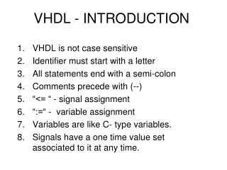
Hardware Description Languages • VHDL = VHSIC Hardware Description Language (VHSIC = Very High Speed Integrated Circuits) • Developed by DOD from 1983 – based on ADA • IEEE Standard 1076-1987/1993/200x • Based on the ADA language • Verilog – created in 1984 by Philip Moorby of Gateway Design Automation (merged with Cadence) • IEEE Standard 1364-1995/2001/2005 • Based on the C language • IEEE P1800 “System Verilog” in voting stage & will be merged with 1364 (Adopted from Profs. Nelson and Stroud)
Anatomy of a VHDL model • “Entity” describes the external view of a design/component • “Architecture” describes the internal behavior/structure of the component • Example: 1-bit full adder A B Cin Full Adder Sum Cout (Adopted from Profs. Nelson and Stroud)
Entity Inputs/Outputs • External view comprises input/output signals (“ports”) • A “port” is defined by its signal name, direction and type: port_name: direction data_type; • direction: • in - driven into the entity from an external source • out - driven from within the entity • inout - bidirectional – drivers within the entity and external • data_type: any scalar or aggregate signal type (Adopted from Profs. Nelson and Stroud)
IEEE Standard 1164 Data Types • Type std_logic data values: ‘U’, ‘X’ – uninitialized/unknown‘0’, ‘1’ – strongly-driven 0/1‘L’, ‘H’ – weakly-driven 0/1 (resistive)‘Z’, ‘W’ - strong/weak “floating”‘-’ - don’t care • Type std_logic_vector is array of std_logic • Include package:library IEEE;use IEEE.std_logic_1164.all; (Adopted from Profs. Nelson and Stroud)
Entity format ENTITY entity_nameIS GENERIC (optional)(generic_name: type :=default_value; … generic_name: mode signal_type); PORT(signal_name: mode signal_type; … signal_name: mode signal_type); END ENTITY entity_name; (Adopted from Profs. Nelson and Stroud)
Full-Adder Adds Three Bits c_in FA h_s (a, b) h_s (h_s(a, b), c_in) XOR sum a XOR HA c_o (a, b) HA c_o (h_s(a, b), c_in) AND b AND OR c_out (Adopted from Profs. Nelson and Stroud)
Entity example (1-Bit Full Adder) ENTITY Full_adder IS PORT ( -- I/O ports a: IN STD_LOGIC; -- a input b: IN STD_LOGIC; -- b input cin: IN STD_LOGIC; -- carry input sum: OUT STD_LOGIC; -- sum output cout: OUT STD_LOGIC); -- carry output END Full_adder ; A B Cin Full Adder Sum Cout (Adopted from Profs. Nelson and Stroud)
Architecture format ARCHITECTURE architecture_nameOF entity_nameIS -- data type definitions (ie, states, arrays, etc.) -- internal signal declarations -- component declarations -- function and procedure declarations BEGIN -- behavior of the model is described here using: -- component instantiations -- concurrent statements -- processes END ARCHITECTURE architecture_name; (Adopted from Profs. Nelson and Stroud)
Dataflow architecture example ARCHITECTURE dataflow OF Full_adder IS BEGIN sum <= a xor b xorcin; cout <= (a and b) or (a and cin) or (b and cin); END dataflow; (Adopted from Profs. Nelson and Stroud)
Structural architecture example ARCHITECTURE structure OF Full_adder IS COMPONENT xor IS -- declare component to be used PORT (x,y: IN STD_LOGIC; z: OUT STD_LOGIC); END COMPONENT xor; COMPONENT or IS -- declare component to be used PORT (x,y: IN STD_LOGIC; z: OUT STD_LOGIC); END COMPONENT or; COMPONENT and IS -- declare component to be used PORT (x,y,z: IN STD_LOGIC; p: OUT STD_LOGIC); END COMPONENT xor; SIGNAL x1,x2,x3,x4: STD_LOGIC; -- signal internal to this component BEGIN G1: xor PORT MAP (a, b, x1); -- instantiate 1stxor gate G2: xor PORT MAP (x1, Cin, Sum); -- instantiate 2ndxor gate G3: or PORT MAP (a, b, x2); -- instantiate 1st or gate G4: or PORT MAP (a, Cin, x3); -- instantiate 2nd or gate G5: or PORT MAP (b, Cin, x4); -- instantiate 3rd or gate G6: and PORT MAP (x2, x3, x4, Cout); -- instantiate and gate END structure; Full-adder (Adopted from Profs. Nelson and Stroud)
Alternative structural architecture example ENTITY half_adder ISPORT (a,b : IN STD_LOGIC ;sum,carry : OUT STD_LOGIC);END half_adder;ARCHITECTURE dataflow OF half_adder ISBEGINsum<= a xor b;carry <= a and b;END dataflow; ENTITY or_2 ISPORT (a,b : IN STD_LOGIC ;c : OUT STD_LOGIC);END or_2;ARCHITECTURE dataflow OF or_2 ISBEGINc<= a or b;END dataflow; ARCHITECTURE structural OF Full_adder ISCOMPONENT half_adderPORT(a,b : IN STD_LOGIC;sum, carry : OUT STD_LOGIC);END COMPONENT;COMPONENT or_2PORT(a,b : IN STD_LOGIC;c : OUT STD_LOGIC);END COMPONENT;SIGNAL int1, int2, int3 : STD_LOGIC;BEGINH1: half_adder port map(a=>A, b=>B, sum=>int1, carry=>int3);H2: half_adder port map(a=>s1, b=>C_in, sum=>sum, carry=>s2);O1: or_2 port map(a=> int2, b=>int3, c=>C_out); END structural; Each Half-adder Full-adder Full-adder (Adopted from Profs. Nelson and Stroud)
Extending full-adder circuit to multiple-bit adition libraryieee; use ieee.std_logic_1164.all; ENTITY adder_4bit IS PORT (a, b: IN STD_LOGIC_VECTOR(3 DOWNTO 0); Cin : IN STD_LOGIC; sum: OUT STD_LOGIC_VECTOR (3 DOWNTO 0); Cout: OUT STD_LOGIC); END adder_4bit; ARCHITECTURE structural OF adder_4bit IS SIGNAL c: STD_LOGIC_VECTOR (4 DOWNTO 0); COMPONENTFull_adder PORT(a, b, c: IN STD_LOGIC; sum, carry: OUT STD_LOGIC); END COMPONENT; BEGIN FA0: Full_adder PORT MAP (a(0), b(0), Cin, sum(0), c(1)); FA1: Full_adder PORT MAP (a(1), b(1), C(1), sum(1), c(2)); FA2: Full_adder PORT MAP (a(2), b(2), C(2), sum(2), c(3)); FA3: Full_adder PORT MAP (a(3), b(3), C(3), sum(3), c(4)); Cout <= c(4); END structural; (Adopted from Profs. Nelson and Stroud)
Behavioral architecture example ARCHITECTURE behavioral OF Full_adder IS BEGIN PROCESS(a, b, cin) BEGIN sum <= a xor b xorcin; cout <= (a and b) or (a and cin) or (b and cin); END PROCESS; END behavioral; ARCHITECTURE behavioral OF Full_adder IS BEGIN Sum: PROCESS(a, b, cin) BEGIN sum <= a xor b xorcin; END PROCESS Sum; Carry: PROCESS(a, b, cin) BEGIN cout <= (a and b) or (a and cin) or (b and cin); END PROCESS Carry; END behavioral; (Adopted from Profs. Nelson and Stroud)
VHDL “Process” Construct • Allows conventional programming language methods to describe circuit behavior • Supported language constructs (“sequential statements”) –only allowed within a process: • variable assignment • if-then-else (elsif) • case statement • while (condition) loop • for (range) loop (Adopted from Profs. Nelson and Stroud)
Process Format [label:] process (sensitivity list) declarations begin sequential statements end process; • Process statements executed once at start of simulation • Process halts at “end” until an event occurs on a signal in the “sensitivity list” (Adopted from Profs. Nelson and Stroud)
D Q CLK Using a “process” to model sequential behavior ENTITY dff IS PORT (d,clk: IN STD_LOGIC; q: OUT STD_LOGIC); END dff; ARCHITECTURE behavioral OF dff IS BEGIN PROCESS(clk) -- “process sensitivity list” BEGIN IF (clk’event and clk=‘1’) THEN q <= d AFTER 1 ns; END IF; END PROCESS; END behavioral; • Process statements executed sequentially (sequential statements) • clk’event is an attribute of signal clk which is TRUE if an event has occurred on clk at the current simulation time (Adopted from Profs. Nelson and Stroud)
D Q CLK Alternative to sensitivity list ENTITY dff IS PORT (d,clk: IN STD_LOGIC; q: OUT STD_LOGIC); END dff; ARCHITECTURE behavioral OF dff IS BEGIN PROCESS -- no “sensitivity list” BEGIN WAIT ON clk; -- suspend process until event on clk IF (clk=‘1’) THEN q <= d AFTER 1 ns; END IF; END PROCESS; END behavioral; • Other “wait” formats: WAIT UNTIL (clk’event and clk=‘1’) WAIT FOR 20 ns; • Process executes endlessly if no sensitivity list or wait statement! (Adopted from Profs. Nelson and Stroud)
Sequential statements in process • if-then-elsif-else statementif condition then (... sequence of statements...)elsifcondition then (... sequence of statements...)else (... sequence of statements...)end if; • case statementcase expression is when choices => sequence of statements when choices => sequence of statements ... when others => sequence of statementsend case; (Adopted from Profs. Nelson and Stroud)
Sequential statements in process • while loop[label:]while condition loop ... sequence of statements ... end loop[label]; • for loop[label:] for loop_variable in range loop ... sequence of statements... end loop [label]; (Adopted from Profs. Nelson and Stroud)
Behavioral architecture example using conditional statements ARCHITECTURE functional OF Full_adder IS BEGIN PROCESS(A,B,Cin) BEGIN If (Cin = '0' and A = '0' and B = '0' ) then sum<= '0'; Cout <= '0'; elsif(Cin = '0' and A = '0' and B = '1') then sum <= '1' ; Cout <= '0'; elsif(Cin = '0' and A = '1' and B = '0' ) then sum <= '1' ; Cout <= '0'; elsif(Cin = '0' and A = '1' and B = '1' ) then sum<= '0'; Cout <= '1'; elsif(Cin = '1' and A = '0' and B = '0' ) then sum <= '1' ; Cout <= '0'; elsif(Cin = '1' and A = '0' and B = '1' ) then sum<= '0'; Cout <= '1'; elsif(Cin = '1' and A = '1' and B = '0' ) then sum<= '0'; Cout <= '1'; elsif(Cin = '1' and A = '1' and B = '1' ) then sum <= '1' ; Cout <= '1'; else sum <= 'X' ; Cout <= 'X'; end if; END PROCESS; END functional; (Adopted from Profs. Nelson and Stroud)
Sequential architecture example ENTITY counter_4bit IS PORT(Ld, Clr, Clk: IN STD_LOGIC; D: IN STD_LOGIC_VECTOR (3 DOWNTO 0); Cout: OUT STD_LOGIC; Qout: OUT STD_LOGIC_VECTOR (3 DOWNTO 0)); END counter_4bit; ARCHITECTURE behavioral OF counter_4bit IS SIGNAL Q: STD_LOGIC_VECTOR(3 DOWNTO 0); BEGIN Qout <= Q; Cout <= Q(3) and Q(2) and Q(1) and Q(0); PROCESS(Clk) BEGIN IF Clk'event and Clk = '1' THEN IF Clr = '0' THEN Q <= "0000"; ELSIF Ld = '0' THEN Q <= D; ELSE Q <= Q + 1; END IF; END IF; END PROCESS; END behavioral; (Adopted from Profs. Nelson and Stroud)
References VHDL mini-reference on Prof. Nelson’s website http://www.eng.auburn.edu/department/ee/mgc/vhdl.html VHDL resources on Prof. Stroud’s website http://www.eng.auburn.edu/~strouce/elec4200.html VHDL resources on Prof. Agrawal’s website http://www.eng.auburn.edu/~agrawvd/COURSE/E6200_Fall10/course.html http://esd.cs.ucr.edu/labs/tutorial/ http://www.seas.upenn.edu/~ese201/vhdl/vhdl_primer.html#_Toc526061344 http://www.vhdl.org/ http://www.doulos.com/knowhow/vhdl_designers_guide/ http://www.altera.com/support/examples/vhdl/vhdl.html http://www.vhdl-online.de/tutorial/ http://www.people.vcu.edu/~rhklenke/tutorials/vhdl/modules/m12_23/sld006.htm http://www.doc.ic.ac.uk/~ih/teaching/lectures/comparch/logic/adder/ (Adopted from Profs. Nelson and Stroud)
Using Modelsim • Modelsim PE (Student Edition) can be downloaded from http://model.com/content/modelsim-pe-student-edition-hdl-simulation?quicktabs_4=1#quicktabs-4 • Modelsim is installed on the Windows7 platform in Lab 310, Broun Hall. (Adopted from Profs. Nelson and Stroud)
Using Modelsim (Adopted from Profs. Nelson and Stroud)
Using Modelsim (Adopted from Profs. Nelson and Stroud)
Using Modelsim (Adopted from Profs. Nelson and Stroud)
Using Modelsim (Adopted from Profs. Nelson and Stroud)
Using Modelsim (Adopted from Profs. Nelson and Stroud)
Using Modelsim (Adopted from Profs. Nelson and Stroud)
Using Modelsim (Adopted from Profs. Nelson and Stroud)
Using Modelsim (Adopted from Profs. Nelson and Stroud)
Using Modelsim (Adopted from Profs. Nelson and Stroud)
Using Modelsim (Adopted from Profs. Nelson and Stroud)
Using Modelsim (Adopted from Profs. Nelson and Stroud)
Using Modelsim (Adopted from Profs. Nelson and Stroud)
Using Modelsim (Adopted from Profs. Nelson and Stroud)
Using Modelsim (Adopted from Profs. Nelson and Stroud)