Download
1 / 17
170 likes | 324 Vues
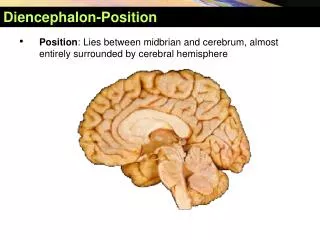
Selection of the New COS/FUV Lifetime Position. Cristina Oliveira. Gain-Sag Artifacts i n COS FUV Spectra. # of events. COS FUV XDL is a photon-counting micro-channel plate (MCP) detector In COS FUV TIME-TAG mode every photon is recorded with: position ( x,y ) and arrival time (t )

E N D
Selection of the New COS/FUV Lifetime Position Cristina Oliveira TIPS Meeting - COS/FUV Lifetime
Gain-Sag Artifacts in COS FUV Spectra # of events • COS FUV XDL is a photon-counting micro-channel plate (MCP) detector • In COS FUV TIME-TAG mode every photon is recorded with: • position (x,y)and arrival time (t) • total electron charge generated/pulse-height amplitude (0 ≤ PHA ≤ 31) • For every detector element, PHA distribution changes with time, shifting to lower PHA values, as fewer electrons can be extracted from the MCP with usage, the so-called gain-sag effect (see top figure) • Events reaching the detector in areas with low PHA are no longer recorded, effectively resulting in a flux loss(see bottom figure) • As time progresses the flux loss can become so severe that the spectrum needs to be moved to a new lifetime position PHA bin (Due to Lya airglow) TIPS Meeting - COS/FUV Lifetime
Timeline of Gain Sag Effects Gain sag holes currently present in COS data By July 2012 will loose part of continuum in FUVA HV to be raised ~March to avoid this By September 2012 will lose part of continuum in FUVB Need to move to new lifetime position before September 2012 TIPS Meeting - COS/FUV Lifetime 3
Moving to a New COS/FUV Lifetime Position: What does it Mean? Constraints on motion of aperture mechanism in Y direction prevents PSA to be moved beyond +/− 6.0” from current position Wavecal location Geocoronal Lya emission Active area of the detector (in pixels) Current Position at 0” +6” +3” 0” −3” −6” COS FUV - Segment B (program 12678,G130M/1291) Jan 17, 2012 4 TIPS Meeting - COS/FUV Lifetime
Parameters Considered in Choosing New COS FUV Lifetime Position In order to choose new lifetime position several factors were considered: • Resolutionat each position • Projected lifetime at each position • Overall flat-field characteristics at each position • Effect of new position on subsequent positions • Use of wavelength calibration lamp spectra at each position • FUV dispersed-light target acquisition at each position • Impact of new lifetime position on aperture mechanism • Resolution and projected lifetime at each position were the most critical parameters in choosing the new COS lifetime position TIPS Meeting - COS/FUV Lifetime
COS FUV Resolution: Cross-Dispersion (Y) Offsets • Resolution at Y offsets inferred assuming R = 19,000 at current position (0.0”) • Resolution at ±3.0” and ±6.0” measured from program 12678 (other values linearly interpolated from nearest on-orbit measurements) • Ray-trace models and on-orbit data predict Ypeak between 0.0” and +3.0” • Positions above current position have better resolution than similar positions below by ~ 20% (e.g., similar resolution between +6.0” and −3.0”) Assumes R0=19,000 at current pos. (0.0”) TIPS Meeting - COS/FUV Lifetime
Resolution: Adding Dispersion (X) Offsets • X offset of 3.0” corresponds ~ to ½ FP-POS • Needed to interlace gain-sag holes due to Lya airglowat each FP-POS position • Mechanism soft stop in +Xdirection allows max offset of +2.0” • Data obtained at +2.0”and −3.0” offsets in X direction with a −3.0” offset in Y (as part of characterization program 12678) • Resolution at (−3.0”,−3.0”) worse than (0”,−3.0”) • Resolution at (+2.0”,−3.0”) similar to (0”,−3.0”) • Ray-trace models support on-orbit results • In X, resolution peaks between 0.0” and +2.0” • Resolution with +2.0” offset in X direction similar to resolution with no offset TIPS Meeting - COS/FUV Lifetime
Resolution: Dispersion + Cross-Dispersion Offset Examples Effect of Y offsets in resolution Effect of Xoffsets in resolution (0.0”, −3.0”) (−3.0”,−3.0”) (0.0”, 0.0”) (0.0”,+3.0”) (0.0”, 0.0”) (0.0”,−6.0”) (0.0”, −3.0”) (+2.0”,−3.0”) TIPS Meeting - COS/FUV Lifetime
Resolution: Summary • Peak of resolution between 0.0” and +3.0” in Y direction • Moves in Y > 0.0” lead to less resolution degradation than similar moves in Y < 0.0” (by ~20%) • Ideally, would like to move to Y = +1.5” (peak as predicted by models). • Need to move further away from current position (at least 3.0”) to avoid existing regions where gain has already sagged • Resolution at +3.0” similar to resolution at current location • Resolution at +6.0” similar to resolution at -3.0” • Peak of resolution between 0.0” and +2.0” in X direction • Offset of +3.0” slightly better to minimize gain sag effects in the first 1-2 yrs • Not feasible due to aperture mechanism constraints • Would likely lead to worse resolution • To optimize resolution best to move as close as possible to +3.0” in Y (with or without X = +2.0” offset) TIPS Meeting - COS/FUV Lifetime
Projected Lifetime at Different Positions The projected lifetime at each position is a function of the initial gain map at the specific position, the detector usage, and how close the new position is to the previous position To determine the projected lifetime at each position: • Data obtained in 12676 were used to model the evolution of gain sag as a function of time and position in the detector • Images were generated for pure Y moves and moves with a -3.0” and +2.0” X offset • Histograms of the modal gain distribution were determined, for the regions where the different gratings project the spectra, for each lifetime position • The % of pixels with modal gain ≤ 3 was determined for each case. • A modal gain of 3 corresponds to a 5% loss in flux TIPS Meeting - COS/FUV Lifetime
G160M/FUVB (0.0”,+3.5”) time = 1 yr (July 2013) G160M/FUVB (0.0”,+3.5”) time = 3 yr (July 2015) MODAL GAIN vs. TIME Dec 09, 2011 TIPS Meeting - COS/FUV Lifetime COS Lifetime Brainstorming 11
Summary: Analysis Modal Gain vs Time and Offset • Positions with Y > 0.0” allow us to mitigate gain sag effects for a longer period of time than similar positions with Y < 0.0” • For FUVB, after ~3 years, the % of pixels with modal gain ≤ 3 is approx. the same regardless of position, indicating that newly formed gain sag regions at that position dominate other effects (except for G140L at -3.0”) • For FUVA, after ~3 years, the % of pixels with modal gain ≤ 3 is much larger for Y < 0.0” than for similar Y > 0.0” positions • G160M spectra are narrower and fall lower in the detector than G130M, leading to asymmetric gain sag structure from the currently used position • The evolution of the modal gain with time for positions at +3.5” or beyond is similar, indicating that they are in a detector location not affected by the gain sag of the current position • The position at +3.0” is not as pristine as that at +3.5”, and after ~3 years it has the double amount of pixels with modal gain ≤ 3 • Positions with X = -3.0” or X = +2.0” offsets are not significantly better at mitigating gain sag than positions without X offsets • Slightly delay gain sag of the Lya regions at the new position in the first 1-2 yrs • So not prolong the overall lifetime of the new position • In ~3 yrs the % of pix with PHA<3 is similar because gain sag at that location dominates • To optimize lifetime at the new position (due to gain sag) best to move to +3.5” or beyond in the Y direction (no huge benefit in moving in X direction) TIPS Meeting - COS/FUV Lifetime
Summary: Analysis of COS Lifetime Positions I • To optimize resolution best to move as close as possible to +3.0” in Y (with or without +2.0” X offset) • To optimize lifetime at the new position (due to gain sag) best to move to +3.5” or beyond in the Y direction (with or without X offset) • X direction offset may be slightly advantageous only in the first 1-2 years because it delays appearance of new gain sag holes • Overall flat-field characteristics don’t change much as a function of Y position, but positive moves are slightly preferred • In terms of bad pixel map, moves with Y > 0.0” are slightly preferred to moves with Y < 0.0”. However, no region is so badly affected as to have a significant weight in the choice of the next lifetime position(s) • Positions in either the positive or negative Y directions lead to flat fields not significantly different from that at current location • Geometric correction accuracy in X and Y comparable for lifetime positions between -6.0” and +6.0” for both segments. No impact in choice of next lifetime position. TIPS Meeting - COS/FUV Lifetime
Summary: Analysis of COS Lifetime Positions II • To optimize the number of lifetime positions, best separation in Y between positions is 3.0”-3.5”. • “Weighted” extraction can be used to reduce separation • Wavecal operations affected only for most extreme positions • Tagflash operations will have to be changed for lifetime positions beyond Y = +5.0”. All other positions can use tagflash without modifications • Only lifetime positions at Y = -4.0” or lower will have to deal with WCA spectrum falling on region of detector potentially affected by gain sag • Target acquisition algorithm will have to be modified for lifetime position at Y = -6.0”. • Other lifetime positions require no modifications • The lifetime of the COS aperture mechanism does not constrain the lifetime positions TIPS Meeting - COS/FUV Lifetime
Constraining the Next Lifetime Position Best location for next lifetime position at Y=+3.5” TIPS Meeting - COS/FUV Lifetime
New COS FUV Lifetime Position and Beyond • The following scenario could be considered for future positions (only next position selected; future positions to be evaluated at later time): Lifetime position 2 at (0”,+3.5”) Lifetime position 3 at (0”,−3.0”) Lifetime position 4 at (0”,+6.0”) –TAGFLASH changes needed to avoid FCA leak issue – • To extend lifetime of each position • Start at low HV and incrementally increase HV to overcome gain sag (modal gain increases by ~ 3 PHA bins per 8 HV steps) • Decrease size of extraction boxes currently used • Use some sort of “weighted extraction” to avoid CALCOS throwing out entire columns when only a few pixels at the edges of extraction box have sagged below the threshold (due to overlap with previously sagged position) • These 3 additional positions will enable us to operate for additional ~ 9 years while mitigating gain sag effects TIPS Meeting - COS/FUV Lifetime
END TIPS Meeting - COS/FUV Lifetime