Time to Digital Conversion Performance Metrics and Tests
490 likes | 700 Vues
Jean-Francois Genat IN2P3/LPNHE Paris IEEE Nuclear Science Symposium and Medical Imaging Conference October 23d 2011, Valencia, Spain. Time to Digital Conversion Performance Metrics and Tests .

Time to Digital Conversion Performance Metrics and Tests
E N D
Presentation Transcript
Jean-FrancoisGenat IN2P3/LPNHE Paris IEEE Nuclear Science Symposium and Medical Imaging Conference October 23d 2011, Valencia, Spain Time to Digital Conversion Performance Metrics and Tests
Key Performance Metrics of Time to Digital Coders and Techniques for their Performance evaluationOutline • Time to Digital conversion • TDC Performance • Tests • Conclusion Time to Digital Conversion Performance Metrics and Tests, October23d 2011, Valencia, Spain
Twoedges as input, a number as output Least significant bit = Input time quantum for one output unit difference t = 1, LSB = 10ns Time to Digital Coding Time to Digital Conversion Performance Metrics and Tests, October23d 2011, Valencia, Spain
Time to Digital Coding • “Coarse” < 1ns (1 GHz) time coding with counters • “Fine” 1-1000ps time coding with either Time to Amplitude Coder and ADC or Digital delay lines phased locked on clock (DLL) Both techniques can be differential or not If a short time range only is required, single TAC or DLL OK. Time to Digital Conversion Performance Metrics and Tests, October23d 2011, Valencia, Spain
Architecture Start Stop Clock Counter Synchro Fine time MSB LSB Sub-multiples Multiples Storage Time to Digital Conversion Performance Metrics and Tests, October23d 2011, Valencia, Spain
Coarse, Fine scales Electronicsdevices - The unit isdefined by the period of a « clock » synchronized on a referencefrequency (e.gquartz, GPS) - Multiples or sub-multiples canbemeasured: Slower: « Counters » dividefrequencies, sub-multiples, « coarse » measurements Faster: « Verniers » multiples of clockfrequency, « fine » measurements Time to Digital Conversion Performance Metrics and Tests, October23d 2011, Valencia, Spain
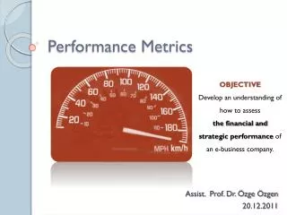
PhysicalInterest Timing resolution Dynamic range Linearity Response time Timing jitter Double pulse resolution Response time Long-termstability Power Integration, package Number of channels … Environment , data acquisition standard, Features Time to Digital Conversion Performance Metrics and Tests, October23d 2011, Valencia, Spain
Key Performance Metrics of Time to Digital Coders and Techniques for their Performance evaluationOutline • Time to Digital conversion • TDC Performance • Tests • Conclusion Time to Digital Conversion Performance Metrics and Tests, October23d 2011, Valencia, Spain
Resolution (binning, time jitter) Full scale (number of bits) Linearities (differential, integral) Number of channels Stop mode, input triggeringcapability Double pulse resolution Maximum input rate Bufferingcapability Response time Referenceclock range Stability (temperature, voltage supply) Encoding, output format, trigger matching Technology, input levels Power, low power mode Package, IP availability,voltage supply Numbers Time to Digital Conversion Performance Metrics and Tests, October23d 2011, Valencia, Spain
Units Time to Digital Conversion Performance Metrics and Tests, October23d 2011, Valencia, Spain
Limitations Coarsemeasurements: Clockjitter Ultimatelyin the ps range withcurrentintegrated CMOS technologies, but the referencedictates the jitter: GPS is 10ns only * Fine measurements: Propagation spreads of delayelements and sensitivity to: Voltage supply Temperature Process variations ADC components used in Time to Amplitude Converters Resolution/Stability *The experiment OPERA at CERN measuredveryrecently 60ns vith an accuracy of 10ns in order to estimate the neutrinos velocity http://cerncourier.com/cws/article/cern/28439 Time to Digital Conversion Performance Metrics and Tests, October23d 2011, Valencia, Spain
Time References: Atomic Clock Chip A few mm3 Courtesy: NIST Time to Digital Conversion Performance Metrics and Tests, October23d 2011, Valencia, Spain
Stability Short time stability: < 1s Long term > 1s Hydrogen clock: 1 femtosecond / second Time to Digital Conversion Performance Metrics and Tests, October23d 2011, Valencia, Spain
Phase noise, jitter Due to any analog noise source in the oscillator (thermal, 1/f…) Carrier: Psignal Sideband Pnoise Power Spectrum: Phase noise as Pnoise/ Psignal in dB/Hz at a givenfrequency offset at one sidefrom the carrier http://smirc.stanford.edu/papers/iwdmic98s-raf.pdf Time to Digital Conversion Performance Metrics and Tests, October23d 2011, Valencia, Spain
Frequencymultiplication: coarse -> fine - The referenceis a devicewhose (time noise) jitterissmall compared to the fine time bin • The Voltage ControlledOscillator (VCO) runsata multiple of • the referencefrequency Time to Digital Conversion Performance Metrics and Tests, October23d 2011, Valencia, Spain
Frequency division Clock : N Counter Counter Start / Stop Memory Time to Digital Conversion Performance Metrics and Tests, October23d 2011, Valencia, Spain
Scaling Sub-multiples: Frequency division using (synchronous) Counters Multiples: Frequency multiplication: Phase LockedLoops 5 MHz clockscaled to 20 MHz and 625 kHz Time to Digital Conversion Performance Metrics and Tests, October23d 2011, Valencia, Spain
To ADC ADC Start Stop Fine timing: Time to Amplitude Converter • A voltage ramp is triggered on ‘Start’, stopped on “Stop” Stop can be a clock edge • Amplitude is coded with a conventional ADC A calibration of the current source isrequired to match a possible concurrent « coarse » measurement Time to Digital Conversion Performance Metrics and Tests, October23d 2011, Valencia, Spain
Differential TAC Same as above, ramp goes up at rate , down at rate Time is stretched by , measured using a regular counter To counter Resolution: a few ps Time to Digital Conversion Performance Metrics and Tests, October23d 2011, Valencia, Spain
Fine timing: Digital Delay Lines • Locked delay line (DLL) or ring oscillator (PLL) if looped Loop of voltage controlled delay elements locked on a clock. • Generation of subsequent logic transitions distant by can be as small as 10-100 ps Clock Delay + time offset controls Time arbiter N delay elements Total delay is half a clock period when locked, the two edges can be locked [J-F. G High Resolution Time to Digital Converters Nucl. Instr. and Meth., Vol 315, N1-3, May 1992, pp 411-415] Time to Digital Conversion Performance Metrics and Tests, October23d 2011, Valencia, Spain
Delay elements Active RC element: R resistance of a switched on transistor C total capacitance at the connecting node Typically RC = 10ps-1ns using current IC technologies N delay elements is technology dependent: the fastest, the best ! Within a chip ~ 1 % a wafer ~ 5-10% a lot ~ 10-20% [Mantyniemi et al. IEEE JSSC 28-8 pp 887-894] Time to Digital Conversion Performance Metrics and Tests, October23d 2011, Valencia, Spain
Time controlled delay element: Starved CMOS inverter Delay controls throughgates voltages PMOS B=A NMOS Propagation delay ~ 10ps-1ns 100ps TDC 0.6 mm CMOS (1992) CMOS Technology 90 nm: >~ 20 ps 45nm < L < 250nm : 65 nm in production today Time to Digital Conversion Performance Metrics and Tests, October23d 2011, Valencia, Spain
Starved CMOS inverter cell (CMOS 130nm) Time to Digital Conversion Performance Metrics and Tests, October23d 2011, Valencia, Spain
Phase lock Clock DLL output Phase arbiter Delay control Lag Lag Lead OK Convergence when the devicelags and leadsalternately Time to Digital Conversion Performance Metrics and Tests, October23d 2011, Valencia, Spain
Y1 Y2 In1 In2 Time arbitration Six transistors implementation in CMOS Issue: metastable states if S and R “almost” synchronous (Spice simlation) Final state depends upon first input activated: in1prior Iin2: Q=1 , Q=0 in1after in2: Q=0, Q=1 [V. Gutnik et al. MIT IEEE 2000 Symp. on VLSI Circuits] Time to Digital Conversion Performance Metrics and Tests, October23d 2011, Valencia, Spain
S Q Q R Time arbitration (FPGA) SR flip-flop in the “forbidden” state ObservedMetastability (from Eric Delagnes) Can beimplemented in an FPGA or IC standard cells (simulateafterrouting !) Time to Digital Conversion Performance Metrics and Tests, October23d 2011, Valencia, Spain
Phase comparator Latched Phase Comparator Time to Digital Conversion Performance Metrics and Tests, October23d 2011, Valencia, Spain
Start t1 SR q0 q1 q2 qn t2 < t1 N cells t2 Stop Differential Delay Lines Time Vernier Fast Stop catches slow Start Time quantum t1-t2 as small as technology spreads allow Nbit = number of bits for ½ LSB precision T = full-scale (maximum time interval to be measured) = delay elements spread [J-F. G High Resolution Time to Digital Converters Nucl. Instr. and Meth., Vol 315, N1-3, May 1992, pp 411-415] Time to Digital Conversion Performance Metrics and Tests, October23d 2011, Valencia, Spain
Time Vernier Work for DELPHI (LEP) Outer Detector (1984 ! ) 500 ps binning, 150ps resolution TDC using digital delay lines 2 mm CMOS Gate Array technology, all digital, but simulated as analog (Spice) This work scaled today : 150 ps x 65nm / 2000nm = 4.8 ps Time to Digital Conversion Performance Metrics and Tests, October23d 2011, Valencia, Spain
Multipulse Time Vernier Multipulse: - Generate vernier referencesatany time - Arbiterwithincomingstart and stops Clock propagated t1 t2 J. Christiansen (CERN), see HPTDC slide Time to Digital Conversion Performance Metrics and Tests, October23d 2011, Valencia, Spain
Full-scale Maximum time to beencoded T = LSB 2N where N is the Number of bits of the device Example: LSB= 10ns, N=16 bits T = 653.6 s Full-scale, Number of bits Time to Digital Conversion Performance Metrics and Tests, October23d 2011, Valencia, Spain
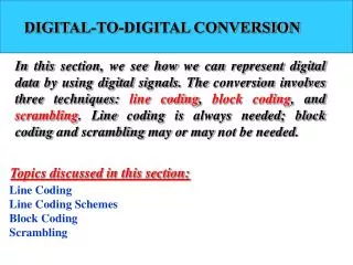
Integrallinearity Differencebetweenwhatshouldbemeasured and whatisactuallymeasured Differentiallinearity Histogram of the binswidths Bothexpressed in LSB unitsrms on the full time range Linearities Time to Digital Conversion Performance Metrics and Tests, October23d 2011, Valencia, Spain
Integrallinearity Differencebetweenwhatismeasured and whatshouldbemeasured Differentiallinearity Histogram of the bin’swidth Can bespecified as maximum or rms in LSB units Integrallinearityis the integral of the differentialone Linearities Time to Digital Conversion Performance Metrics and Tests, October23d 2011, Valencia, Spain
Linearities for a 6 bit, 500ps LSB, 32ns full-scale CMOS TDC Linearities: Example Time to Digital Conversion Performance Metrics and Tests, October23d 2011, Valencia, Spain
Number of channels Number of independentchannels inputs on an (IC) device, usually a power of 2 (e.g 32, 64). May sharesomecontrols: Clock, Common start, Common stop, Gate Triggering A channelmaybetriggered by an input levelabove a programmable threshold, the time and address are recorded in an event buffer Number of channels, Stop modes, Triggering Time to Digital Conversion Performance Metrics and Tests, October23d 2011, Valencia, Spain
Picosecond chips Digital • Vernierdelay lines offer 5–100 ps resolution for multi-channel chips Full custom: 25ps J. Christiansen, CERN 8ps J. Jansson, A. Mantyniemi, J Kostamovaara, OlouUniv(Finland) Analog • 10ps TAC chip available from ACAM (2 channels) if channel rate < 500 kHz, 40ps @40 MHz GHz Analog Memories PSI (Stefan Ritt) 8GHz Timing resolution 10ps Hawaii (G. Varner 6 GHz Timing resolution 4ps Chicago (H. Frisch) 15 GHz Planned 2ps (under evaluation) Time to Digital Conversion Performance Metrics and Tests, October23d 2011, Valencia, Spain
The CERN High Precision TDC (HPTDC) The HPTDC is a high performance IC TDC with a highly flexible data driven architecture that allows it to be used in many different applications. The architecture was originally developed for the use within the ATLAS and CMS muon detectors and for the ALICE Time Of Flight (TOF) detector. The HPTDC chip has now been used by a multitude of different applications in particle physics and other research areas. The HPTDC can work in two major modes:Low resolution: 32 channels with 100ps resolutionHigh resolution: 8 channels with 25ps resolution Commercial general purpose TDC modules have also been made based on the HPTDC: CAEN: V1190A, V1190B, V1290ABluesky electronics, Cronologic. http://tdc.web.cern.ch/tdc/hptdc/hptdc.htm 37 Time to Digital Conversion Performance Metrics and Tests, October23d 2011, Valencia, Spain
Picosecond electronics Becker & Hickl Germany 5ps rms @ 200 MHz Time to Digital Conversion Performance Metrics and Tests, October23d 2011, Valencia, Spain
ACAM 10ps TDC http://www.acam.de/products/time-to-digital-converters// 39 Time to Digital Conversion Performance Metrics and Tests, October23d 2011, Valencia, Spain
ACAM 10ps TDC 40 Time to Digital Conversion Performance Metrics and Tests, October23d 2011, Valencia, Spain
Key Performance Metrics of Time to Digital Coders and Techniques for their Performance evaluationOutline • Time to Digital conversion • TDC Performance • Tests • Conclusion Time to Digital Conversion Performance Metrics and Tests, October23d 2011, Valencia, Spain
TDC test benches Can also use test bencheswith standard instrumentation such as: - CAMAC - Fastbus - VME • IEEE 488 (GPIB) • ATCA (very new) Test software: Sendrandomstarts/stops withsufficientstatistics and buildhistograms Evaluatelinearities, stability 42 Time to Digital Conversion Performance Metrics and Tests, October23d 2011, Valencia, Spain
TDC tests Pulse generators http://www.quantumcomposers.com/item/9530-series.html 43 Time to Digital Conversion Performance Metrics and Tests, October23d 2011, Valencia, Spain
TDC tests Pulse generators http://www.greenfieldtechnology.com/IMG/pdf/GFT1004.pdf 44 Time to Digital Conversion Performance Metrics and Tests, October23d 2011, Valencia, Spain
TDC tests Pulse generators http://www.highlandtechnology.com/DSS/V880DS.shtml 45 Time to Digital Conversion Performance Metrics and Tests, October23d 2011, Valencia, Spain
Key Performance Metrics of Time to Digital Coders and Techniques for their Performance evaluationOutline • Time to Digital conversion • TDC Performance • Tests • Conclusion 46 Time to Digital Conversion Performance Metrics and Tests, October23d 2011, Valencia, Spain
Conclusion Time to Digital Coders reach the picosecond range resolution Many flavours, from various Deep Submicron CMOS technologies IC implementations Today, 10 ps is integrated with regular CMOS IC processes In all case, layout is more than critical as far as the psrange is targeted Promising results from even thinner VLSI CMOS technologies in terms of • Resolution • Dynamic range - Power - Number of Channels 47 Time to Digital Conversion Performance Metrics and Tests, October23d 2011, Valencia, Spain
Y. Arai and M. Ikeno, “A Time Digitizer CMOS Gate-Array with a 250 ps Time Resolution”, IEEE Journal of Solid-State Circuits, Vol. 31, No.2, Feb. 1996, p.212-220. Reference - Y. Arai and M. Ikeno, “A Time Digitizer CMOS Gate-Array with a 250 psTime Resolution”, - IEEE Journal of Solid-State Circuits, Vol. 31, No.2,Feb. 1996, p.212-220. - A. Mantinyemi ”An Integrated CMOS High Prcision Time-To-Digital Converter Based On Stabilised Three Stage Delay Line Interpolation “ PhD dissertation, University of Oulu, Finland (2004) - M. Mota et al., “A Four Channel, Self-calibrating, High Resolution TDC,” Proceedings of the 5th IEEE International Conference on Electronics Circuits and Systems (ICECS’98), Lisbon, Sept 1998. - M. Mota, J. Christiansen, “A High-Resolution Time Interpolator Based on a DLL and a RC Delay Line”, IEEE JSSC, Vol 34, n°10, Oct 1999. Audoin & Guinot,1998, Les fondements de la mesure du temps, Masson, ISBN 2-225-83261-7; Time to Digital Conversion Performance Metrics and Tests, October23d 2011, Valencia, Spain