DIGITAL-TO-DIGITAL CONVERSION
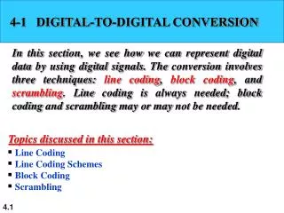
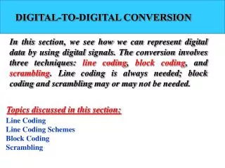
DIGITAL-TO-DIGITAL CONVERSION. Line Coding Line Coding Schemes Block Coding Scrambling. Signal Encoding Techniques. Digital Data, Digital Signal. d igital signal discrete, discontinuous voltage pulses each pulse is a signal element binary data encoded into signal elements. Terminology.

DIGITAL-TO-DIGITAL CONVERSION
E N D
Presentation Transcript
DIGITAL-TO-DIGITAL CONVERSION Line Coding Line CodingSchemesBlock Coding Scrambling
Digital Data, Digital Signal • digital signal • discrete, discontinuous voltage pulses • each pulse is a signal element • binary data encoded into signal elements
Terminology • unipolar – all signal elements have the same sign • polar – one logic state represented by positive voltage and the other by negative voltage • Bipolar -- A binary 0 is encoded as zero volts as in unipolar encoding. A binary 1 is encoded alternately as a positive voltage and a negative voltage. • data rate – rate of data ( R ) transmission in bits per second • duration or length of a bit – time taken for transmitter to emit the bit (1/R) • modulation rate – rate at which the signal level changes, measured in baud = signal elements per second. • mark and space – binary 1 and binary 0
Nonreturn to Zero-Level (NRZ-L) • easiest way to transmit digital signals is to use two different voltages for 0 and 1 bits • voltage constant during bit interval • no transition (no return to zero voltage) • absence of voltage for 0, constant positive voltage for 1 • more often, a negative voltage represents one value and a positive voltage represents the other(NRZ-L)
Non-return to Zero Inverted (NRZI) • Non-return to zero, invert on ones • constant voltage pulse for duration of bit • data encoded as presence or absence of signal transition at beginning of bit time • transition (low to high or high to low) denotes binary 1 • no transition denotes binary 0
NRZ Pros & Cons • lack of synchronization capability • NRZ-L and NRZ-I both have a DC component problem. • used for magnetic recording • not often used for signal transmission
Binary Bipolar-AMI • use more than two signal levels • Bipolar-AMI • binary 0 represented by no line signal • binary 1 represented by positive or negative pulse • binary 1 pulses alternate in polarity • no loss of sync if a long string of ‘1’s occurs • no net dc component • lower bandwidth • easy error detection In bipolar encoding, we use three levels: positive, zero, and negative.
Multilevel Binary Pseudoternary • binary 1 represented by absence of line signal • binary 0 represented by alternating positive and negative pulses • no advantage or disadvantage over bipolar-AMI and each is the basis of some applications
Theoretical Bit Error Rate The multilevel binary signal requires approximately 3 dB more signal power than a two-valued signal for the same probability of bit error.
Polar biphase: Manchester Encoding • transition in middle of each bit period • midbit transition serves as clock and data • low to high transition represents a 1 • high to low transition represents a 0 • used by IEEE 802.3
Polar biphase: Manchester and differential Manchester schemes
Differential Manchester Encoding • midbit transition is only used for clocking • transition at start of bit period representing 0 • no transition at start of bit period representing 1 • this is a differential encoding scheme • used by IEEE 802.5
Normalized Signal Transition Rate of Various Digital Signal Encoding Schemes Table 5.3
Scrambling • use scrambling to replace sequences that would produce constant voltage • these filling sequences must: • produce enough transitions to sync • be recognized by receiver & replaced with original • be same length as original • design goals • have no dc component • have no long sequences of zero level line signal • have no reduction in data rate • give error detection capability
B8ZS (Bipolar with 8-zero substitution) scrambling technique (USA) a. Proceeding pulse is positive; 8 zero are coded as 000+-0-+; b. Proceeding pulse is negative; 8 zero are coded as 000-+0+-;
Note Multilevel schemes: increase the number of bits per baud. In Multilevel (mBnL) schemes, a pattern of m data elements is encoded as a pattern of n signal elements in which 2m≤ Ln.
Multilevel: 2B1Q (2 binary, 1 quaternary) scheme, used in DSL