Download
1 / 20
210 likes | 346 Vues
Spin-Transfer switching with short current pulses in all perpendicular spin valve nanopillars. Huanlong Liu 1* , Daniel Bedau 1 , Jean-Jacques Bouzaglou 1, 4 , Andrew D. Kent 1 , Jordon A. Katine 2 , Eric E. Fullerton 3 , Stephane Mangin 4.

E N D
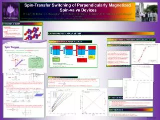
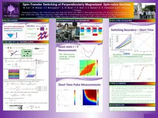
Spin-Transfer switching with short current pulses in all perpendicular spin valve nanopillars Huanlong Liu1*, Daniel Bedau1, Jean-Jacques Bouzaglou1, 4, Andrew D. Kent1, Jordon A. Katine2, Eric E. Fullerton3, Stephane Mangin4 1Department of Physics, New York University, New York, NY, USA. 2Hitachi-GST, San Jose, CA, USA 3CMRR, University of California, La Jolla, CA, USA 4Institut Jean Lamour, Nancy Université, Vandoeuvre, France *hl757@nyu.edu March Meeting 2010
Introduction – all perpendicular geometry • High energy barrier for magnetization reversal in small elements. • Small critical current in thermally stable elements. • High symmetry. Mangin et al., Nat. Mat. (2006) Mangin et al., APL (2009) Bedau et al., APL (2010) March Meeting 2010
Sample Design [Co/Ni] x 4 • Co/Ni free layer, 1.6 nm thick • Co/Ni – Co/Pt hard layer • high coercive field (> 0.5 T) • Measured > 20 samples • Present results on: • 100 nm x 100 nm • 50 nm x 50 nm samples easy axis Cu Free Layer [Co/Ni] x 2 / [Co/Pt] x 4 Hard Layer March Meeting 2010
Room Temperature I – V measurements + B - Size: 50 nm x 50 nm Current Source Iap – p = 0.4 mA Ip – ap = -1 mA Rac = 20 Ω MR = 0.3 % March Meeting 2010
I – V Phase Diagram 100 nm x 100 nm 50 nm x 50 nm Rac = 20 Ω δRac = 70 mΩ Rac = 6 Ω δRac = 25 mΩ March Meeting 2010
Measure Switching Probability 1 2 Current Pulse 3 ? B = 0.2 T B = 0 T Apply measurement field and current Saturate Check if switched Apply pulse If switched go here If NOT switched go here 4 Apply the same pulse 100 – 10,000 times March Meeting 2010
Switching Probability – 100 nm x 100 nm Switching Diagram (Happ = 0) 50 % Boundaries slope -0.06 T X intercept 0.0 T Current pulse Field direction AP – P March Meeting 2010
Switching Probability – 50 nm x 50 nm Switching Diagram (Happ = 0) 50 % Boundaries 0.0 T -0.1 T Current pulse Field direction AP – P March Meeting 2010
A and Ic0 – Macrospin Model 100 nm x 100 nm 50 nm x 50 nm m0HC= 0.25 T, a = 0.011, P = 0.015 m0HC = 0.23 T, a = 0.03, P = 0.02 Θ0 = 1.1 rad Θ0 = 1.36 rad Θ0 = 0.05 rad Θ0 = 0.05 rad A(-0.06 T) = 0.325 x 10¹² (s-1 A-1) – exp Ic0(0T) = 5.04 mA – exp A(0 T) = 1.38 x 10¹² (s-1 A-1) – exp Ic0(-0.1T) = 1.31 mA – exp A(-0.06 T) = 5.00 x 10¹² (s-1 A-1) – fit Ic0(0T) = 3.15 mA – fit A(0 T) = 1.31 x 10¹² (s-1 A-1) – fit Ic0(-0. 1T) = 1.31 mA – fit March Meeting 2010
Conclusion • Fast switching in all-perpendicular spin valves. • Switching boundaries take the form of in short time domain. • Macrospin model does not describe field dependence of dynamic behavior. Bedau et al., Appl. Phys. Lett. 96, 022514 (2010) March Meeting 2010
Thank you ! March Meeting 2010
Switching for all time domains Size: 100 nm x 100 nm Zero applied field AP – P Ic0 = 6.57 mA March Meeting 2010
Macro Spin Model • Landau-Lifshitz-Gilbert (LLG) equation + Spin Torque: where: and For apply field and current along easy axis: we can get: ignore thermal effects in process – J. Z. Sun, P.R.B. 2000 March Meeting 2010
Macro Spin Model • And the result will be: where: is the final (initial) angle and is time This result will be linearized as: to analyze the experimental data March Meeting 2010
Macro Spin Model – large current expansion Large dA / dH requires large Only angles depend on field if still wants to fit A requires results small large Ic0 is normal results small March Meeting 2010
I – V measurement + Current Source B - Size: 100 nm x 100 nm Rac = 6 Ω MR = 0.3 % Iap – p = 4 mA Ip – ap = -7 mA March Meeting 2010
Pulse Transmission through Sample Bottom Top • 2.5 ns pulse from generator and transmitted through the sample • 200 ps rise / fall time, 0.4 V output amplitude. March Meeting 2010
A and Ic0 – full model 100 nm x 100 nm 50 nm x 50 nm Barely fit, but with large initial angles Cannot fit • Strong variation of A with field. • Large initial angle. • Process faster than predicted. March Meeting 2010
A and Ic0 – linear model 100 nm x 100 nm 50 nm x 50 nm Θ0 = 0.51 rad, m0HK = 0.2086 T, a = 0.0475, P = 0.095 Θ0 = 1.36 rad, m0HK = 0.245 T, a = 0.0115, P = 0.015 March Meeting 2010
Information – all @ 0 T • Minimum energy switching: • 100 nm: 660 ps, 0.9 pJ • 50 nm : 826 ps, 0.05 pJ • Energy Barrier: • 100 nm: 0.245 T, 8.7 eV = 338 kT • 100 nm: long time, ~ 2 eV = 78 kT • 50 nm: 0.23 T, 2.04 eV = 78 kT • Ic0 / Uk: • 100 nm: 6.57 mA / 338 kT = 19.4 uA / kT • 50 nm: 1.31 mA / 78 kT = 16.8 uA / kT • Compare dynamics: March Meeting 2010