Comprehensive Overview of Global Trigger System in CMS Experiment
Detailed description of the Global Trigger System in CMS experiment, showcasing its components, principles, algorithm logic, and input specifics for physics running.

Comprehensive Overview of Global Trigger System in CMS Experiment
E N D
Presentation Transcript
CMS Level-1 Trigger Nov. 2000
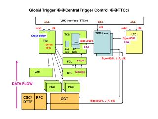
Global Trigger For physics running the Global Trigger uses only input from the calorimeters and the muon system. Trigger specific sub-detector data are used. The high resolution data are used by the Higher Level Triggers. Apart from the trigger data, special signals from all sub-systems may be used for calibration, synchronization and testing purposes (technical triggers). The TTC System is an optical distribution tree that is used for the transfer of the Level-1 Accept signal and timing information (LHC clock etc.) between the trigger and the detector front-ends. The Trigger Control System controls the delivery of L1A signals and issues bunch crossing zero and bunch counter reset commands. There is a facility to throttle the trigger rate in case of buffers approaching overflow conditions. The Event Manager controls the Higher Level Triggers and the Data Acquisition. Global Trigger Environment Nov. 2000
Examples of Trigger Conditions Trigger Examples of explorable physics channels 1 m HSM, H, A, H±, W, W’, t, B-physics channels 2 m HSM, h, H, A, Z, Z’, V, , LQ, Bs0 ->2m, , ’, ’’ m+e/g HSM, H, A, t, WW, WZ, Wg, , V m+jet(s)HSM, h, H, A, , LQ, t m+ETm t, , LQ, WW, WZ, Wg 1 e/g HSM, h, H, A, W, W’, t, B-physics channels 2 e/g HSM, h, H, A, Z, Z’, WW, WZ, Wg, , LQ 2 jets QCD e/g+jet(s) HSM, h, H, A, , LQ, QCD (g +jets, W+jets) m+t HSM, H, A, e/g+t HSM, H, A, t+jets H± jets+ETm , H± Nov. 2000
Basic Principles of the Global Trigger For most other comparable experiments the trigger is based on counting objects exceeding thresholds. Only summary information is available. This implies applying thresholds at local or regional levels. In CMS, only the Global Trigger takes decisions, i.e. no cuts (except inherent thresholds for defining a jet, isolation criteria etc.) are applied by lower level trigger systems. The trigger decision is based on detailed information about a trigger object, which includes not only pT or ET, but also location. For muons, quality information and charge are also available. This enables selecting specific event topologies. The objects are ordered by rank. An algorithm is a combination of trigger objects satisfying defined threshold, topology and quality conditions. There are 128 trigger algorithms running in parallel. The resulting bits are available in the trigger data record. The Global Trigger runs dead-time free by principle, i.e. a L1 Accept/Reject decision is issued with every bunch crossing. The Trigger Throttle System may, however, inhibit a L1A in case of e.g. buffer overflow warning. For each algorithm a rate counter and a programmable prescale factor (up to 16 bits) are available. The L1 decision is taken by a Final OR of which up to 8 are available for physics. Nov. 2000
Input to Global Trigger Best 4 isolated electrons/photons ET, h, f Best 4 non-isolated electrons/photonsET, h, f Best 4 central jets ET, h, f Best 4 forward jets ET, h, f Best 4 t- jets ET, h, f Total ETSET Missing ETETmiss, f(ETmiss) 6 jet counts (central jets) 2 jet counts (forward jets) Best 4 muons pT, sign, f, h, quality, MIP, ISO 4 inputs (approximately 100 bits) are still free. Nov. 2000
Board Layout of the Global Trigger PSB (Pipeline Synchronizing Buffer) Input synchronization GTL (Global Trigger Logic) Logic calculation FDL (Final Decision Logic) L1A decision TIM Timing GTFE (Global Trigger Frontend) Readout Nov. 2000
Algorithm Logic The Algorithm Logic is performed in the GTL boards located in the Global Trigger crate. The first step consists of applying conditions to groups of trigger objects: Particle Conditions and Delta Conditions. This step is sufficient for many algorithms already. Algorithm calculations requiring more complex correlations between different particles are performed in a second step, the so called Algorithm AND-OR. Object configurations can not only be selected, but also vetoed. Nov. 2000
Particle Conditions Particle Conditions are applied to a group of objects of the same type. The conditions are: ET or pT thresholds, h/f-windows, bit patterns for isolation, quality, charge, and spatial correlations (Dh, Df) between objects of the same type. Particle Condition for 2 back-to-back isolated electrons Particle Condition for 2 back-to-back isolated opposite-sign muons with MIP bits set Nov. 2000
Delta Conditions Delta Conditions refer to the calculation of spatial correlations (Dh, Df) between objects of different types. The correlations are restricted to “close” and “opposite/far”. This is actually also the case for same type objects. More detailed angular relations can be calculated by the Higher Level Triggers. Nov. 2000
Algorithm AND-OR Next step: Actual algorithm calculations. Logical combinations (AND-OR) of objects are determined. Nov. 2000
Algorithm AND-OR Nov. 2000
Basic Trigger Setup In the stable phase of the experiment the trigger is set up via Run Control using predefined menus which include reasonable thresholds for different luminosities. These thresholds may be changed by the physicist, without reconfiguring the logic chips. Most of the 128 algorithms are available for physics running. The basic rule is to keep the trigger menus as simple as possible. If not all interesting physics processes can be caught with these, more sophisticated logic may be used, but careful studies of trigger efficiencies have to be made. If a new algorithm (i.e. one not already present on the chips) becomes necessary, the chips can be reprogrammed by experts. The timescale for this is a few hours, but it should not happen too often. Nov. 2000
Example for Expert Setup Procedure Setup- and Placement Program Event Generator Nov. 2000
Overview of Features and Flexibility The trigger logic is largely programmable. Particle energy or momentum thresholds and h (or f) windows can be set separately for each object. Different thresholds for central and forward regions are therefore possible. Templates for muon quality, including MIP, isolation and charge information can be selected. Space correlations are possible between all objects, but restricted to “close” and “opposite/far”. Jets are actually separated into central and forward jets. There are also 8 jet multiplicities, 2 of which are reserved for the forward jets. Nov. 2000