Advancements in X-Band Technology for Future Particle Physics Colliders
180 likes | 292 Vues
The international science community is undertaking a significant long-term mission focused on understanding particle physics at the TeV energy scale. The establishment of X-Band technology is crucial, enabling concurrent operation of the LHC and linear collider. This report outlines the construction timeline, starting with the 8-Pack Phase-I PPM Klystrons and the development of a SLED-II rf system, which will enhance the feasibility of a linear collider. Key milestones include upcoming power tests and advancements in structure fabrication, vital for achieving the necessary energy reach for future colliders.

Advancements in X-Band Technology for Future Particle Physics Colliders
E N D
Presentation Transcript
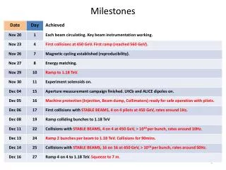
Status and Milestones D. L. Burke ISG9 KEK December 10-13, 2002
Mission and Strategy There is compelling reason to establish the X-Band technology soon. • The international science community is taking on a 20-year mission to understand particle physics at the TeV energy scale. • The LHC and a linear collider must have periods of concurrent operation to reinforce and guide each other, just as the case has been in the past. • Construction and commissioning of a linear collider will take ~ 8 years. Making a choice of linac technologies will enhance the probability that a linear collider is built and ready in time to meet this mission. We must accelerate the demonstration of an X-Band rf system … and we must do it with no increase in level of funding.
8-Pack Phase-I PPM Klystrons (75 MW 1.6 µsecs) Power to loads in March 2003. Dual-Mode SLED-II (4-fold compression in time, factor 3.3 in power) “Single Feed” RF Pulse (500 MW 400 nsec)
NLC/JLC(X) SLED-II Baseline • Phase-I of the 8-Pack will demonstrate the feasibility of a SLED-II rf system similar to that presently in use at the NLCTA. • This demonstration will occur in 2003. • JLC and NLC physicists presented to the world community (ILC-TRC) a SLED-II Baseline Design for an X-Band collider. The “R1s” • SLED-II Power Demonstration • Structure Gradients
The Test Accelerator The NLCTA with 1.8 m accelerator structures (ca 1997). RF Power from SLAC Demonstrated ability to reach 500 GeV cms. Accelerating gradient of 25 MV/m (loaded) with good wakefield control and energy spread. Structures from KEK.
X-Band RF Systems NLCTA SLED-II System (1997) • Conventional PFN modulator • 50 MW/1.2s solenoid-focused klystrons • SLED-II pulse compression • 1.8m DDS structures at 40 MV/m X-Band TeV SLED-II System (2002) • Solid-state modulator • 75 MW/1.6s PPM-focused klystrons • Dual mode SLED-II pulse compression • 0.9m DDS structures at 65 MV/m
NLC/JLC SLED-II Baseline Test NLCTA Housing Dual-Mode SLED-II Solid-State Modulator Solenoid-Focused Klystrons (to be replaced with PPM tubes).
SLED-II Demonstration Status • Modulator is on-line and driving a pair of XL-4 klystrons. • Third XL-4 klystron being installed, and fourth being conditioned in the Test Lab. • All SLED-II designs passed microwave “cold tests” and components are in production. • On schedule for power tests to loads in March 2003. Permanent magnet focused klystrons (one each from KEK and SLAC) scheduled for test in February.
Dual-Mode SLED IILow-Power (Cold) Tests First Reflection (TE02) Input Pulse (TE01) Second Reflection (TE01) 320 ns
RF Pulse Heating T53VG3 Performance limited by pulse heating of coupler matching irises. Distribution of Breakdowns (70 MV/m, 400 ns, 10 hr run) Autopsy performed after high-gradient testing. Rate in cells .1/hr Input coupler 58 Cells Output coupler Beam’s eye view of input coupler. RF RF SEM picture of input matching iris. Pulse heating in excess of 100° C.
RF Matching Cell Mode Conversion Coupler Mode Conversion (MC) Coupler |Es|max= ~34 MV/m @ 48 MW |Hs|max= ~98.4 kA/m @ 48 MW Pulse Heating ~ 3° C WC90 WR90 RF TM01 Mode Launcher
1 Trip / 25 Hours 1Trip / 25 Hours NLC/JLC Trip Requirement: < 1 per 10 Hours at 65 MV/m 400 ns Pulse Width Operations of T53VG3MC (Mode Conversion Couplers) Unloaded Gradient (MV/m) Time with RF On (hr)
High-Gradient R&DSummary Test structures exceed the design goal of 65 MV/m for the JLC/NLC TeV collider. Remains to complete fabrication and test of “NLC/JLC-Ready” structures with full detuning and damping. • First tests of a/l = 0.18 structures (with bad couplers) look good, and testing of structures (with good couplers) is starting. • Will start testing full-featured structures in May to satisfy TRC R1 items. There is a broadly-based line-up of structures in design and fabrication at SLAC, KEK, Fermilab, and CERN. Schedule.
X-Band Accelerator with Length for 500 GeV/Beam 32 km 3.5 km Why X-Band? Bypass Lines e.g. 50, 175, 250 GeV Injector Systems for 1.5 TeV
NLC/JLC Energy Reach 25 Bunches CMS Energy (GeV) 192 Bunches Luminosity (1034) The JLC/NLC Stage 2 design luminosity is 5 1033 cm-2 s-1 at 1.3 TeV cms.
Energy Goals The energy reach of NLC/JLC is significantly greater than that of TESLA (for comparable cost). This will be the central issue in the choice of technology. • HEPAP 2001 “… 500 GeV … expandable to 800-1000 GeV …” • ECFA 2001 “… 400 GeV …” • ACFA 2001 “… initial 300-500 GeV … upgrade to greater than 1 TeV.” The international community needs to reach a consensus on the importance of access to the highest energies.
ILC-TRC Interim ReportICFACERN, October 2002 • “By the end of 2003, we hopefully should know if TESLA can reach 800 GeV at 35 MV/m.” • “By the end of 2003, we hopefully should know if JLC/NLC can meet its main linac [TeV] RF system specifications.” • “If yes, then the International Community could make a choice based on the other respective merits of these machines.”
NLC-JLC Collaboration Our job is to prepare for this technology choice. • Complete the critical R&D (TRC R1 and R2) • Update and document the X-Band Baseline design. • Understand site requirements and cost estimates. ISG9 will focus on this job.