Engineering Drawing Lecture 5 PROJECTION THEORY
University of Palestine College of Engineering & Urban Planning First Level. Engineering Drawing Lecture 5 PROJECTION THEORY. Lecturer: Eng. Eman Al.Swaity Eng.Heba hamad. PART 1. PROJECTION METHOD. Projection methods. Orthographic projection. TOPICS. Perspective. Parallel. Oblique.

Engineering Drawing Lecture 5 PROJECTION THEORY
E N D
Presentation Transcript
University of Palestine College of Engineering & Urban Planning First Level Engineering Drawing Lecture 5 PROJECTION THEORY Lecturer: Eng. Eman Al.Swaity Eng.Heba hamad
PART 1 PROJECTION METHOD
Projection methods Orthographic projection TOPICS
Perspective Parallel Oblique Orthographic Axonometric Multiview PROJECTION METHOD
The projection theory is used to graphically represent 3-D objects on 2-D media (paper, computer screen). The projection theory is based on two variables: 1) Line of sight 2) Plane of projection (image plane or picture plane) PROJECTION THEORY
There are 2 types of LOS : Line of sight Line of sight Line of sightis an imaginary ray of light between an observer’s eye and an object. parallel converge and Parallel projection Perspective projection
The image is produced by connecting the points where the LOS pierce the projection plane. Plane of projection Plane of projection Plane of projectionis an imaginary flat plane which the image is created. Parallel projection Perspective projection
Disadvantage ofPerspective Projection Perspective projection is not used by engineer for manu- facturing of parts, because 1) It is difficult to create. 2) It does not reveal exact shape and size. Width is distorted
Object views from top 1 2 3 4 1 2 3 4 5 5 Projection plane MEANING Orthographic projectionis a parallel projection technique in which the parallel lines of sight are perpendicular to the projection plane
ORTHOGRAPHIC VIEW Orthographic view depends on relative position of the object to the line of sight. Rotate Two dimensions of an object is shown. Tilt More than one view is needed to represent the object. Multiview drawing Three dimensions of an object is shown. Axonometric drawing
Both drawing types are used in technical drawing for communication. ORTHOGRAPHIC VIEW NOTES Orthographic projection technique can produce either1. Multiview drawingthat each view show an object in two dimensions. 2. Axonometric drawingthat show all three dimensions of an object in one view.
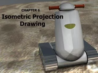
Axonometric (Isometric) Drawing Advantage Easy to understand Disadvantage Shape and angle distortion Example Distortions of shape and size in isometric drawing Circular hole becomes ellipse. Right angle becomes obtuse angle.
Multiview Drawing Advantage It represents accurate shape and size. Disadvantage Require practice in writing and reading. Example Multiviews drawing (2-view drawing)
PART 2 Orthographic Projection
Object representation Multiview projection Glass box concept Orthographic projection of point, line, plane, surface and object. Line convention Isometric Sketching TOPICS
Axonometric projection Multiview projection OBJECT REPRESENTATION
Depth Height Depth Width Height Width Depth MULTIVIEW PROJECTION Three principle dimensions of an object … … can be presented only two in each view. Adjacent view(s) is needed tofulfill the size description.
TO OBTAIN MULTIVIEW REPRESENTATION OF AN OBJECT • Revolve the object with respect • to observer. • The observer move around the • object.
REVOLVE THE OBJECT Right side view Front view (Elevation) (Elevation) Top view
OBSERVER MOVE AROUND Top view Front view Right side view
THE GLASS BOX CONCEPT Rear view Left side view Bottom view
History Depth Width Height
Orthographic Projection of Object Features
OBJECT FEATURES are lines that represent the boundarybetween two faces. Edges Represent the intersection of two ormore edges. Corners Edge Edge No edge Corner No corner No corner
Surface Surface Surface OBJECT FEATURES are areas that are bounded by edges or limiting element. Surfaces is a line that represents the last visible part of the curve surface. Limitingelement Limit Limit
Equal distance PROJECTION OF POINT(S) BT BT AT AT B A BR AF BF BR AR AF BF AR
PROJECTION OF LINE True length BT AT BT Equal length AT B A BR AF BF AF BF AR BR AR Point True length NORMAL LINE
PROJECTION OF LINE True length BT AT BT Equal length AT B A A AF BR BF AF BF AR BR AR Foreshortened Foreshortened INCLINED LINE
PROJECTION OF LINE Foreshortened BT AT BT B Equal length BR BF AT B A BF BR AF A AF AR AR Foreshortened Foreshortened OBLIQUED LINE
PROJECTION OF PLANE True size CT BT CT AT Equal length BT AT C B CR A BF AF,CF BF AF,CF CR AR,BR AR,BR Edge Edge NORMAL PLANE
PROJECTION OF PLANE Foreshortened CT BT CT AT C Equal length BT AT CR CF C B CF CR A BF AF AR,BR BF AF AR,BR Edge Foreshortened INCLINED PLANE
PROJECTION OF PLANE Foreshortened CT BT CT AT C Equal length B CR BT AT BF CF C B CF BR BR CR BF A AF AR AF AR Foreshortened Foreshortened OBLIQUED PLANE
PROJECTION OF OBJECT The views are obtained by projecting all object features to the picture plane. (Elevation) You have to project the remaining surfaces which are invisible too !
s s s PROJECTION OF OBJECT (Elevation)
PROJECTION OF OBJECT (Elevation)
LINE CONVENTION Precedence of coincide lines. Hidden line drawing. Center line drawing.
PRECEDENCE OF LINE Order of importance Visible line Hidden line Center line
HIDDEN LINE PRACTICE Hidden line should join a visible line, except itextended from the visible line. Leave space Correct Join No !
HIDDEN LINE PRACTICE Hidden line should join a visible line, except itextended from the visible line. Leave space Leave space Correct No !
HIDDEN LINE PRACTICE Hidden line should intersect to form L and Tcorners. L Correct T No !
HIDDEN LINE PRACTICE Hidden arcs should start on a center line.
CENTER LINE PRACTICE In circular view, short dash should cross at the intersections of center line. For small hole, center line is presented as thin continuous line. Center line should not extend between views. Leave space Leave space
CENTER LINE PRACTICE Leave the gap when centerline forms a continuation with a visible or hidden line Center line should always start and end with long dash. Leavespace Leavespace Leavespace Leavespace
Isometric Sketching
Sketch from an actual object 1. Place the object in the position which its shape and features are clearly seen. 2. Define an isometric axis. 3. Sketching the enclosing box. 4. Estimate the size an and relationship of each details. 5. Darken all visible lines.
Sketch from an actual object STEPS 1. Positioning object. 2. Select isometric axis. 3. Sketch enclosing box. 4. Add details. 5. Darken visible lines.
In isometric sketch/drawing), hidden lines are omittedunless they are absolutely necessary to completelydescribe the object. Note Sketch from an actual object STEPS 1. Positioning object. 2. Select isometric axis. 3. Sketch enclosing box. 4. Add details. 5. Darken visible lines.
End of The Lecture PROJECTION THEORY